
Quick Answer
Safety capacitors are classified by where they sit on a mains supply and by what their failure must not cause. An X capacitor bridges live and neutral, where a short is a fire risk. A Y capacitor bridges a supply rail to earth, where a short would put mains onto something a person can touch.
Safety
This lesson deliberately publishes no rated voltage, impulse voltage or test level attributed to any standard. The classification of these parts, and the subdivisions inside each class, are defined by international standards that this page does not quote, because a wrong figure quoted against a class is the worst error a page like this can contain. Every number below is arithmetic on capacitances and a supply voltage this lesson chooses for itself. When you specify a real part, the class marking on its body and its own datasheet are the authority, and a capacitor in either of these positions must always be a part actually approved for it.
Intuition
A door that must swing outward
Fire regulations do not ask whether a door is strong. They ask which way it opens. A door that opens inward can be held shut by a crowd pressing against it, so in a place where a crowd might need to leave, the door must open outward. The requirement is not about the door's quality; it is about which failure mode is acceptable.
Safety capacitors are specified the same way, and it is the only place in this department where a component's classification is a statement about how it is allowed to break rather than about what it does while working. Both classes are ordinary capacitors doing an ordinary job: shunting high-frequency noise so it does not leave the appliance along the mains lead, or arrive along it. The classification is entirely about the consequence when one of them fails.
Two positions, two consequences. A capacitor connected across the line, between live and neutral, sits inside the appliance's own wiring. If it fails as a short it puts a fault across the supply, and the consequence to worry about is fire. A capacitor connected from a supply rail to earth is a different matter: earth in a Class I appliance is bonded to the metalwork the user touches, so a short there connects a person to the mains.
Those two are the X class and the Y class, and everything about how they are built, sized, tested and marked follows from which of those two consequences is being prevented.
Practitioner
Position, consequence, and the number each one is allowed
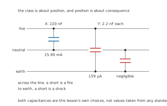
The class is about position, and position is about consequence.
Worked example — Why one is a hundred times the other
An X capacitor of 220 nF across a 230 V supply at 50 Hz has a reactance of 14.47 kΩ and passes 15.90 mA. That current circulates between live and neutral inside the appliance and reaches nobody, so its size is a matter of loss rather than of safety: the reactive power it moves is 3.656 var.
A Y capacitor of 2.2 nF from live to earth has a reactance of 1.447 MΩ and passes 159 µA. That current flows in the earth conductor, and if the earth conductor is ever missing it flows through whoever is holding the appliance.
The ratio between the two is 100.0, and the entire reason for it is where the current can go.
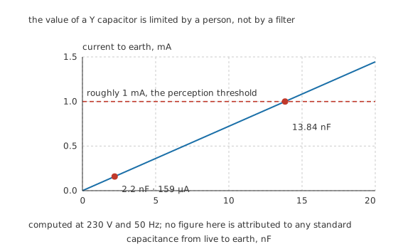
The value of a Y capacitor is limited by a person, not by a filter.
The straight line is the whole design constraint. Filter designers would always like more capacitance to earth, because it is the most effective place to put it. What stops them is that the current in that path is proportional to the capacitance, and it has a person at the end of it.
Roughly 1 mA is the perception threshold electrical safety publishes, the level at which a current begins to be felt. Reaching it from a 230 V supply would take 13.84 nF to earth, so the 2.2 nF part above sits comfortably below it. But the limit that actually applies to a product is a leakage-current limit set by the standard the product is built to. It is usually stricter than perception, and it counts every path in the appliance together rather than one capacitor at a time.
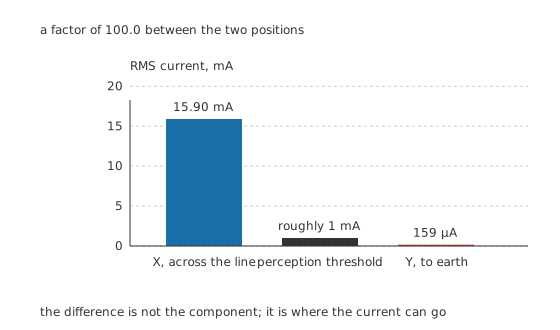
The difference is not the component. It is where the current can go.
Engineer
Built to fail in the permitted direction
Both classes are metallised film capacitors, and that is not a cost decision. A metallised film part clears its own punctures: the plate is a layer of aluminium tens of nanometres thick, so a fault vaporises the metal around itself and isolates it. The part loses an immeasurable amount of capacitance and stays a capacitor.
For a component whose classification is a promise about failure, that mechanism is the whole design. A ceramic capacitor in either of these positions would be unacceptable regardless of its rating, because a cracked ceramic fails as a short, and both classes exist specifically to prevent a short.
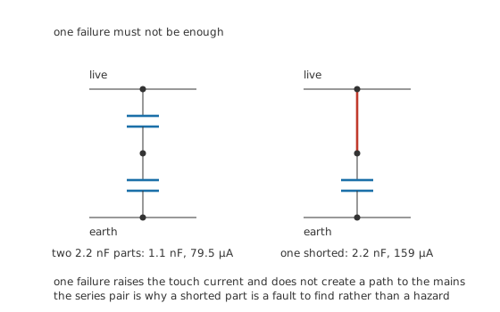
One failure raises the touch current and does not create a path to the mains.
Where the consequence is severe enough, the design does not rely on self-healing alone. Two Y capacitors in series across the same insulation barrier give 1.1 nF and pass 79.5 µA. If one of them fails shorted, the remaining part is still 2.2 nF passing 159 µA: twice as much current, still far below the perception threshold, and still an insulator between the mains and the user. A single component failure becomes a fault to be found at the next service rather than a hazard.
That is the same reasoning that puts the class letters in front of a subdivision. Within X and within Y there are grades, and the grade says which insulation barrier the part is qualified to bridge and how severe a surge it is expected to survive in that position. Those grades are defined numerically by a standard, and this lesson does not quote those numbers, because a wrong impulse voltage set against a class letter would be exactly the kind of error that gets a part fitted in a position it is not qualified for.
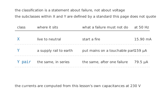
The classification is a statement about failure, not about voltage. The subclasses come from a standard this page does not quote.
What is safe to carry away without a datasheet in front of you is the shape of the decision:
The position determines the class. Across the line is X. To earth or to a touchable part is Y. A part cannot be moved between the two positions on the strength of its voltage rating.
The class marking is on the body. A part approved for either position carries its class, and usually a set of approval marks alongside it. A capacitor without that marking has not been qualified for the position, whatever its rating says, and an ordinary film capacitor rated for hundreds of volts is not a substitute.
The barrier being bridged determines the grade. A Y capacitor bridging basic insulation and one bridging reinforced insulation are different grades. That is a decision to take from the product's own safety standard, and it is not a judgement to make from first principles.
Professional
The resistor that always comes with it
An X capacitor sits directly across live and neutral, which means it also sits directly across the pins of the plug. Pull the plug at the peak of the cycle and the capacitor is left charged at 325.3 V, with the pins exposed and a person's fingers a few centimetres away.
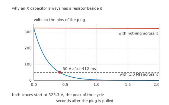
Both traces start at 325.3 V, the peak of the cycle.
With a 1.0 MΩ discharge resistor across it, the time constant is 220 ms and the voltage is below 50 V after 412 ms. Without one, an illustrative 1.0 GΩ of the capacitor's own leakage gives a time constant of 220 s, and the same fall takes 412 s: nearly seven minutes with a live-feeling plug in somebody's hand.
That is why an X capacitor in a mains input filter always has a resistor across it, why the requirement is written into product standards as a maximum discharge time, and why a missing or open discharge resistor is a real fault rather than a cosmetic one. Voltage ratings and derating sets out the general case; this is the version of it with a person in the circuit.
What goes wrong in service
The capacitor ages and loses value. Every self-healing clearing costs a little plate area, and a part that has spent a decade across a mains supply in a warm enclosure has cleared many faults. The filtering degrades quietly, and an appliance that used to pass its emissions test does not.
It fails open. The self-healing mechanism taken to its conclusion. Filtering disappears entirely, and nothing else changes, so the fault is invisible without a measurement. Testing capacitors is where that measurement lives, and a capacitance well below the marked value is the evidence.
The discharge resistor fails open. Then the plug stays live to the touch for minutes after unplugging. The capacitor is fine and the appliance works normally.
Somebody substitutes an ordinary capacitor. The most dangerous of the four, and it happens during repair. A general-purpose film capacitor of the same value and a comfortable voltage rating looks like a valid replacement and is not, because the rating it lacks is a qualification about failure, not about volts. A safety capacitor is replaced only by a safety capacitor of the same class or better.
Where the class boundary really bites
The one judgement worth internalising is that these classifications do not scale with voltage in the way the rest of this department does. Everywhere else in the capacitors school, a higher voltage rating is a safe substitution and a bigger part is a conservative choice. Here, a part rated for twice the voltage but not approved for the position is not a conservative choice at all; it is an unapproved one.
And in the Y position, a larger capacitance is actively worse. More capacitance is more current to earth, and the limit on that current is a limit on what a person may be exposed to. This is the only place in the department where fitting more capacitance than the design called for makes a product less safe rather than more sluggish. Choosing the right capacitor treats the general selection problem; this position is the exception to almost every rule in it.
Common mistakes
- Substituting an ordinary film capacitor for a safety capacitor — the class marking is a qualification about how the part fails, not a voltage rating. A general-purpose part of the same value and a higher voltage rating is not an equivalent.
- Fitting a larger Y capacitance for better filtering — the current to earth is proportional to the capacitance and it has a person at the end of it. Bigger is worse in this position, uniquely in this department.
- Assuming an unplugged appliance's X capacitor is discharged — without a working discharge resistor it can hold hundreds of volts on the plug pins for minutes.
- Using a ceramic capacitor in either position — ceramic fails as a short, and both classes exist to prevent a short.
- Treating the class letter as a voltage rating — the letters describe position and failure consequence. The numbers behind the subdivisions come from a standard, and guessing them puts parts in positions they are not qualified for.
Frequently asked questions
What is the difference between an X and a Y capacitor?
Where they are connected, and therefore what their failure would cause. An X capacitor bridges live and neutral, where a short is a fire risk. A Y capacitor bridges a supply rail to earth or to a touchable part, where a short would connect a person to the mains. Both are metallised film parts chosen because that construction clears its own faults instead of shorting.
Why are Y capacitors such small values?
Because the current they pass flows to earth, and if the earth connection is ever missing it flows through a person instead. That current is proportional to the capacitance, so the value is limited by a leakage-current limit rather than by what the filter would prefer. A few nanofarads is typical; tens of nanofarads to earth would not be.
Can I replace a safety capacitor with an ordinary one of the same value?
No. The class marking is a qualification about how the part behaves when it fails, and an ordinary capacitor has not been through it. A higher voltage rating does not substitute for the qualification. Replace a safety capacitor only with an approved part of the same class or better.
Why does an X capacitor need a resistor across it?
Because it is connected directly across the plug pins. If the plug is pulled near the peak of the mains cycle, the capacitor is left charged at that peak and the exposed pins are at that voltage. A discharge resistor brings it down in a fraction of a second; without one it can take minutes.
Why are two Y capacitors sometimes fitted in series?
So that one failure is not enough. If either part fails shorted, the other still stands between the mains and the user, and the touch current merely doubles from a small figure to a slightly larger small figure. A single component failure becomes a fault to find rather than a hazard.