
Quick Answer
Testing a capacitor is two jobs in order: prove it is discharged, then find out what it is worth. Capacitance, series resistance and leakage each answer a different question, none of them answers all three, and the test frequency changes what the meter reads.
Safety
A capacitor taken out of equipment can hold a charge that is dangerous, and the ones that hold most are exactly the ones people reach for: reservoir capacitors behind a rectifier, sitting at hundreds of volts. Discharge every such part deliberately and then measure it to confirm, because an assumption is not a measurement. Discharging through a resistor rather than a screwdriver keeps the energy out of an arc and out of the part. Every number in this lesson is arithmetic on stated component values rather than a measurement of equipment, and nothing here is a procedure for working on a live appliance.
Intuition
Proving the room is empty before locking it
A building's closing routine is not a walk around the corridors. It is a check, room by room, with a record: not because anybody expects to find somebody in there, but because the cost of being wrong once is far larger than the cost of checking every time. The routine exists to convert a belief into a fact.
Testing a capacitor starts with that same conversion, and the belief being tested is that it is discharged.
A 220 µF capacitor charged to 400 V holds 17.6 J. That is not an abstract quantity: it is enough energy to weld a screwdriver tip, blow a crater in a probe, and pass a very unpleasant current through a hand. The capacitor may have been sitting in a drawer for a week. It does not care.
So the sequence is fixed. Discharge it deliberately, through a resistor. Measure across the terminals to confirm. Then, and only then, start finding out whether the part is any good.
The second half of the job turns out to be more interesting than most people expect. There are three separate measurements a capacitor can be given, they answer three different questions, and a part can pass any one of them while failing another. The meter that most people own answers only one of the three.
Practitioner
Discharging it, and confirming
Worked example — Sizing the discharge resistor
Put 1.0 kΩ across the 220 µF part charged to 400 V. At the first instant the resistor dissipates 160 W, so it has to be a part that survives a brief burst of that, and the burst is brief: the time constant is 220 ms.
The voltage falls below 50 V after 457.5 ms. Leave the resistor on for a few seconds and the part is genuinely at nothing.
The whole 17.6 J ends up in the resistor, which is why a wirewound or a bulk part is the right choice and a small film resistor is not.
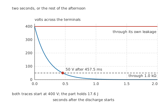
Two seconds, or the rest of the afternoon.
The second trace is the reason the confirming measurement matters. Left to its own leakage, the same part takes hours rather than seconds, and there is nothing about its appearance that distinguishes the two cases.
There is a further wrinkle worth knowing about, because it surprises people who did everything right. A capacitor that has been shorted and then released does not always stay at zero: dielectric absorption returns some of the charge over the following seconds and minutes. Film capacitors works through the mechanism with millivolt-scale examples; on a large high-voltage part the recovered voltage is far larger than that. The habit that deals with it is to leave the discharge resistor connected while working, rather than discharging once and moving on.
Engineer
Three measurements, three different questions
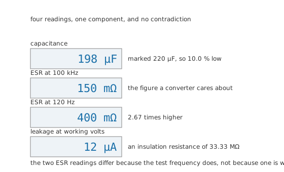
Four readings, one component, and no contradiction.
Capacitance answers whether the part still holds what it says. A reading of 198 µF against a marked 220 µF is 10.0 % low, which is inside an ordinary electrolytic's tolerance and also consistent with a part halfway through its life. The measurement alone cannot tell those apart, which is the recurring difficulty with this test: it needs a reference.
Series resistance answers whether the charge can get out, and it is the more sensitive test. ESR roughly doubles over a part's life while the capacitance moves only a fifth, so a rising ESR shows up first. It is also the measurement that finds bad joints, since a poor connection is in series with the part and reads as if it were part of it.
Leakage answers whether the insulation is intact.
A leakage of 12 µA at 400 V is an insulation resistance of 33.33 MΩ, and that resistance sets a self-discharge time constant of 7.333 ks, which is 2.037 hours.
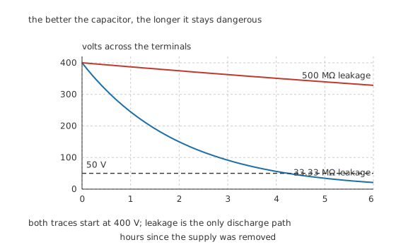
The better the capacitor, the longer it stays dangerous.
A cleaner part at 500 MΩ has a time constant of 110 ks and takes 63.54 hours to fall to a safe level. Low leakage is a virtue in the circuit and a hazard on the bench, and the two facts are the same fact.
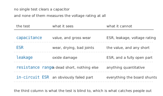
No single test clears a capacitor, and none of them measures the voltage rating at all.
Two things no bench test reaches, and they are worth stating plainly because a clean set of readings invites the opposite conclusion. The voltage rating cannot be measured without applying the voltage, which is a destructive test on a part that may be the reason the equipment failed. And behaviour under working conditions is not what a meter's small test signal produces: a part that measures perfectly at a few millivolts can still misbehave under bias, ripple or temperature.
Professional
Why two meters disagree about the same part
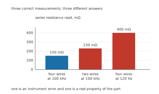
Three correct measurements, three different answers. One is an instrument error and one is a real property of the part.
Two different mechanisms are at work in that picture, and separating them is most of the skill in this measurement.
The frequency is a real property. A part's series resistance falls with frequency, because part of it is dielectric loss rather than metal. Measured at 120 Hz this part reads 400 mΩ, and at 100 kHz it reads 150 mΩ, a factor of 2.67. Both are correct. Which one matters depends on the job: a reservoir behind a mains rectifier works at the low figure, and a capacitor in a switching converter works at the high one. Comparing a reading against a datasheet figure taken at a different frequency is comparing two different quantities.
The leads are an instrument error.
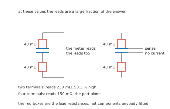
The red boxes are the lead resistances, not components anybody fitted.
With two terminals, the current that drives the measurement and the voltage that reads it share the same wires, so 40 mΩ at each end is inside the answer. A part whose real resistance is 150 mΩ reads 230 mΩ, which is 53.3 % high. Four-terminal connection separates the two paths: the sense wires carry no current, so they develop no voltage, and the reading is the part alone. At these values that is not a refinement, it is the difference between a useful number and a meaningless one. The multimeter and LCR meters cover the instruments themselves.
Testing in circuit, and when not to bother
An in-circuit ESR check is fast and it is the standard first move on a suspect power supply, because the board's other components mostly do not shunt a low resistance at the test frequency. It has two honest limitations. Everything in parallel with the part is inside the reading, so the answer is an upper bound rather than a measurement. And a good reading does not clear the part, because capacitance and leakage were never measured.
A capacitance measurement in circuit is usually worthless, because anything in parallel adds to it and the reading is a fiction.
The judgement that follows is a practical one. Use in-circuit ESR to find an obviously bad part quickly. Remove the part when the reading is ambiguous, when the value matters, or when leakage is the suspicion. And where several identical parts sit on one board, measure all of them: the comparison between siblings is often more informative than any absolute reading, because they have shared a history and a temperature.
What the readings are worth without a reference
Everything in this lesson depends on knowing what the part looked like new. A datasheet gives it, a new part of the same type gives it, and a sibling that has run cooler gives an approximation. Without any of those, a single set of readings establishes only that the part is not obviously dead. That is worth knowing and it is not the same as good, and failure modes and ageing is where the drift those readings are looking for comes from.
Common mistakes
- Assuming a capacitor is discharged because the equipment is unplugged — a part with low leakage can stay dangerous for hours. Discharge deliberately through a resistor and confirm with a meter.
- Discharging a large capacitor with a screwdriver — the energy goes into an arc, the part and the tool. A resistor takes the same energy without any of that.
- Comparing an ESR reading against a datasheet figure at a different frequency — a part's series resistance genuinely falls with frequency, so the two numbers are different quantities rather than a disagreement.
- Measuring low ESR with two-terminal leads — the lead resistance is inside the answer, and at tens of milliohms that is most of it. Four-terminal connection is what makes the reading mean anything.
- Concluding a part is good from one clean reading — capacitance, series resistance and leakage answer different questions, and no bench test measures the voltage rating at all.
Frequently asked questions
How do I safely discharge a capacitor?
Through a resistor, not a screwdriver, and then confirm with a meter. Choose the resistance so the initial dissipation is survivable for a moment and the time constant is short enough to be convenient, then leave it connected while you work, because dielectric absorption can return a voltage after the short is removed.
Can I test a capacitor with an ordinary multimeter?
Partly. Many meters measure capacitance, which finds a badly degraded or open part. Very few measure series resistance, which is the more sensitive indicator, and almost none measure leakage at working voltage. A resistance range finds only a dead short.
Why do two meters give different ESR readings for the same capacitor?
Usually the test frequency. A capacitor's series resistance falls as frequency rises, so a meter testing at a hundred hertz and one testing at a hundred kilohertz report genuinely different figures for the same part. The other cause is lead resistance, which a two-terminal measurement includes in the answer.
Can I test capacitors without removing them from the board?
For series resistance, usually yes, and it is the standard quick check on a power supply. The reading is an upper bound because anything in parallel is included, and a good reading does not clear the part because the value and the leakage were not measured. In-circuit capacitance measurements are generally not worth making.
How do I know whether a reading is good if I have no datasheet?
Compare. A new part of the same type is the best reference, and a sibling on the same board that has run cooler is a useful one. Where several identical parts are fitted, the spread between them often says more than any single absolute reading.