
Quick Answer
A digital multimeter measures voltage, current and resistance, and a few other quantities besides. Which one it measures is set by two things at once: the rotary switch, and which pair of sockets the leads are plugged into. Getting those two to agree is most of using one safely.
Intuition
What the display is really telling you
A multimeter puts a number on the front panel. The number is honest, and it is honest about something quite specific: the meter reports what exists between the two probe tips while the probes are held there, on the range and in the mode the switch has selected.
Miss any part of that and the number misleads. A meter set to volts and held across a resistor reports the potential difference between its ends. The same meter, same probes, same resistor, switched to ohms, reports something else entirely, and on a powered board reports nonsense. The instrument has not changed its mind. The question it was asked did.
Most of a meter's front panel exists to state that question. The rotary switch names the quantity. The sockets, called jacks, decide what the meter physically is while it does the job: a very large resistance in one pair, a very small one in another. And the digits count in steps the meter's converter can produce, so the last one moves in jumps rather than smoothly.
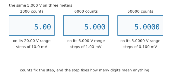
A basic meter reaching 5.000 V does it on a 20.00 V range in steps of 10.0 mV. A better one covers the same voltage on a 6.000 V range in steps of 1.00 mV, and a bench instrument on 5.0000 V in steps of 0.100 mV. All three are correct about the voltage. What separates them is the size of the smallest change each can report, and that is a property of the meter's converter rather than of the voltage.
Practitioner
Working through the ranges
The sequence below is short and the order is deliberate. Steps 1 and 2 exist because of what Layer 3 describes, and skipping them is how meters die.
- Decide what you are measuring and select it on the switch before anything is plugged in anywhere.
- Put the leads in the jacks that match. The black lead lives in the common jack permanently. The red one moves: volts and ohms share one jack, and current has its own, sometimes two of them for different maximum currents.
- Choose a range that comfortably holds the expected reading, or leave the meter to autorange if it does that. Where you do not know the magnitude at all, start at the highest range and work down.
- Make the black connection first and the red one second, and take them off in the reverse order. That keeps a live probe from being the only thing in your hand.
- Read the mode annunciators, not only the digits. A displayed "OL" means the reading is off the top of the range, not zero. A minus sign means the probes are the other way round, which is information rather than an error.
- Let the reading settle. A meter takes several readings a second and averages, so a figure caught in the first instant of contact is often not the final one.
- Return the red lead to the volts jack when you have finished. This is a habit rather than a step, and Layer 3 explains what it prevents.
A meter's resolution is set by its counts: the number of distinct steps its converter can produce over a range. Divide the range by the count and you have the smallest change the display can show.
Worked example — Why the range matters more than the meter
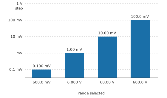
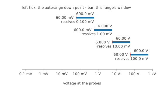
A 6000-count meter carries four voltage ranges: 600.0 mV, 6.000 V, 60.00 V and 600.0 V.
On the 600.0 mV range it resolves 0.100 mV. Move up to 6.000 V and the step becomes 1.00 mV, ten times coarser. The 60.00 V range steps by 10.00 mV and the 600.0 V range by 100.0 mV.
The same meter is therefore a thousand times finer at the bottom of its span than at the top, and a reading of a small voltage taken on a high range throws that away. An autoranging meter does the selection for you; a manual one gives you the chance to get it wrong.
Safety
The rule this lesson exists to teach: a meter with its leads in the current jacks is a piece of wire, and placing a piece of wire across a source is a short circuit through your instrument and through your hands. On a battery bench that destroys a fuse and, on the evidence in Layer 3, the meter behind it; on mains wiring the same mistake can produce an arc flash, which is a different order of event entirely and one this lesson's own numbers do not cover.
Return the red lead to the volts jack the moment a current measurement is finished, before the meter is put down. The next person to pick it up, including you tomorrow, will reach for volts.
Use a meter and leads whose CAT rating covers the installation you are working in. That rating describes the transient energy the instrument is built to survive at a given point in a supply system, and a standard sets out what each category means and how the instrument is tested; the categories are not interchangeable and a higher number is not simply a higher voltage. As a rough guide, the categories run from CAT I to CAT IV and track how close the point being probed sits to where a fault's energy is limited by the utility supply itself. CAT IV covers the service entrance and the main distribution equipment feeding a building. CAT III covers permanently wired branch circuits and the distribution panels downstream of that. CAT II covers ordinary plug-in equipment and the wall outlets that feed it. CAT I covers circuits that never connect to the supply directly, such as the low-voltage side of some bench equipment. Match the category to where the probes actually go, not to the voltage you expect to read, because a low voltage on a badly categorised circuit can still deliver a high-energy fault. CAT ratings and safe working voltages gives the full treatment, including the numbers this paragraph deliberately leaves out.
Meters with fused current jacks exist so that this fault is survivable, and the fuse in them is specified for the fault energy it may have to interrupt. A wire wrapping, a nail or an ordinary glass fuse pushed into that holder defeats the entire protection. Replace a blown current fuse only with the type the manufacturer specifies.
Everything in electrical safety fundamentals applies here, and the general practice for live work is set out there rather than repeated.
Engineer
Counts, digits and what they buy
The digits on the display come from a converter that produces a whole number of counts, and the range decides what one count is worth. Resolution stops there. Accuracy is a separate question: a meter can step in 1.00 mV and still be wrong by twenty times that. Accuracy, resolution and measurement error separates the two properly.
Older meters were sold by digit count, where a leading digit that can only be zero or one counts as a half. A meter described that way with three and a half digits reaches 2000 counts. The count figure is the more useful description, because 6000 and 50000-count meters both exist and neither has a tidy digit name.
What the meter is, in each pair of jacks
In the volts jacks, the meter is a large resistance, typically 10 MΩ, held across whatever is being measured. It takes a small current of its own, and on high-resistance circuits that current is enough to shift the reading. Meter loading effects works that through.
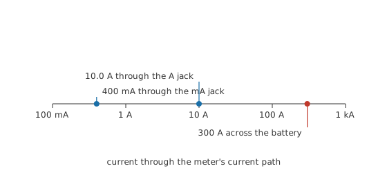
In the current jacks, the meter is a shunt: a small, precise resistance placed in a break in the circuit, with the meter reporting the voltage across it. Those jacks carry their maximum on the panel beside them, often 400 mA for the low one and 10.0 A for the high one. On the high range the shunt might be 10 mΩ, which is less than most pieces of wire on your bench.
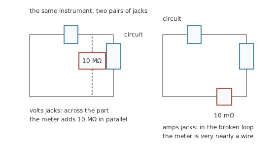
Put that second thing across a source and there is nothing to limit the current but the source itself. Take a 12.0 V lead-acid battery of 20 mΩ internal resistance, reached through 10 mΩ of lead. The shunt, the battery and the leads are the only three resistances in the loop, and together they come to 40 mΩ:
which works out at 300 A, with 900 W in a shunt built for a fraction of a watt. Those figures are arithmetic on the three resistances above, not a measurement, and there is no version of this experiment worth performing. What the arithmetic buys you is the reason the habit in Layer 2 is not fussiness.
Ranges, autoranging and the window each one covers
An autoranging meter steps up when a reading exceeds the present range and steps down when it falls well below it, leaving a deliberate gap between the two thresholds so a signal sitting near a boundary does not send the meter hunting. The cost is time: each change takes a moment, and a manual range is faster when you already know the magnitude.
What the AC ranges assume
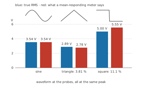
A cheap meter measures AC by rectifying it, averaging, and multiplying by a constant. That constant is chosen so a sine wave comes out right, which means the meter is correct for sines and wrong for everything else. Take three shapes at the same peak of 5.00 V:
The sine's true RMS value is 3.54 V and the meter says 3.54 V, as designed. A triangle's true 2.89 V comes back as 2.78 V, low by 3.81 %. A symmetric square wave, whose RMS value equals its peak at 5.00 V, is reported as 5.55 V, high by 11.1 %. A true RMS meter computes the actual root-mean-square instead and is right about all three, within its own specified crest-factor limit.
Professional
Beyond the handheld meter
A handheld meter answers steady questions. It samples a few times a second and shows an average, so anything happening faster than that is invisible to it, and a display that reads a comfortable rail voltage says nothing about a fault lasting a microsecond. That gap is what the oscilloscope exists to fill, and the two instruments answer different questions rather than competing ones.
The extra functions on the switch each carry assumptions of their own. Capacitance ranges charge the part with a known current and time the result, so they want it discharged and out of circuit. Frequency counters gate an internal reference against the input. Temperature ranges take a thermocouple and do the cold-junction correction internally. Duty-cycle readings assume a two-level signal and a threshold somewhere between the levels. The manual is where those assumptions are written down, and ten minutes with it saves an afternoon later.
Bench and handheld instruments diverge above about the fifth digit. Bench meters use slower converters that reject mains-frequency interference by integrating over a whole number of mains cycles, offer four-wire resistance connections, and can be driven remotely by a computer. A handheld meter trades all of that for a battery, a rubber case and the ability to reach inside a machine.
Input protection is a design rather than a promise. The volts jacks are built to survive transients well above the meter's rated range, and the current jacks are protected by their fuses and by the CAT rating of the whole instrument. Both protections are specified against a standard test, and both assume the instrument is intact. A cracked case, a lead with damaged insulation or a fuse replaced with the wrong part removes the protection while changing nothing the user can see.
A few readings are not what they appear to be. The ohms range applies a small test voltage, deliberately below the forward drop of a silicon junction so that semiconductors nearby stay switched off, and continuity and diode test modes turn that fact into two useful tests. The DC volts range on a circuit carrying AC as well reports the average of both, which is correct and often unhelpful. And on a floating circuit, the probes and the meter can sit at any potential the circuit chooses, so a comfortable-looking reading may be taken between two points that are both live with respect to earth.
A number written down without its conditions is worth less than it looks: the range, the mode, where in the circuit, and what else was running at the time. That note costs a line in a notebook and turns a set of readings into evidence, which is where measuring voltage, current and resistance picks the subject up.
Common mistakes
- Leaving the red lead in the current jack. Meters are destroyed this way more than any other, and so are the fuses, the leads and occasionally the circuit. Make it reflex to move the lead back.
- Reading the digits without reading the annunciators. An "OL" is a range problem, not a measurement, and a meter on the wrong function will happily show a plausible number.
- Measuring resistance on a powered circuit. The ohms range works by pushing its own current through the part, and any other current present corrupts the result or damages the meter.
- Trusting a cheap meter's AC range on anything but a sine. Chopped mains, pulse-width drives and switching supplies all produce shapes it was never calibrated for.
- Working on a high range out of caution and then reading a small voltage from it. Caution belongs in the first reading; the second should be on the range that resolves what you are looking at.
- Assuming a low resistance reading proves a good connection. The ohms range and the beeper both have a threshold, and a joint that passes either can still be far too resistive to carry working current.
Frequently asked questions
What do the counts on a multimeter mean?
Counts are the number of distinct steps the meter's converter can produce across one range. Divide the range by the counts and you get the smallest change the display can show. A 6000-count meter on a 6.000 V range steps in 1 mV.
Is a meter with more counts more accurate?
Not by itself. Counts describe resolution, which is how finely the meter can divide a range. Accuracy describes how close the reading is to the truth, and it comes from a separate specification. A meter can display four decimal places and be wrong in the second.
Why did my meter blow its fuse?
Almost always because the leads were still in the current jacks when the probes went across a voltage. In that configuration the meter is a low resistance placed across a source, and the fuse is what stands between that mistake and the rest of the instrument.
Do I need a true RMS meter?
For sine waves, no. For anything with a distorted or chopped waveform — a dimmer, a variable-speed drive, a switching supply, a rectified rail — a mean-responding meter can read several per cent out in either direction, and the error depends on a shape you may not know.
Why does my meter read a voltage on a wire that is not connected to anything?
The input resistance is high but not infinite, so a floating input picks up stray coupling from nearby wiring and shows it. The reading usually collapses the moment a real load is present. It is a genuine signal, and it is not the circuit's.