
Quick Answer
Troubleshooting a DC circuit is the practice of locating a fault by comparing measured voltages against the values the circuit should produce. The method is to work on a live circuit, halve the suspect region with each new reading, and let the pattern of drops name the fault before any part is replaced.
Intuition
A fault shows up as a voltage out of place
A circuit that has stopped working still obeys every rule it obeyed while it worked. Something in it has changed — a joint that has come apart, a cracked track, a part that has failed outright — and the result is voltages sitting where the design never put them. Fault-finding is the work of measuring those voltages and finding the one that disagrees with what the design says it should be.
Take three equal resistors of 1 kΩ each, joined one after another across 12 V. Working properly, the same 4 mA passes through all three, and a voltmeter with its black lead parked on the supply's negative terminal — the reference point every reading is compared to — shows 8 V at the junction after the first resistor and 4 V at the junction after the second. Neither figure needed a meter to be known: both follow from the parts and the supply.
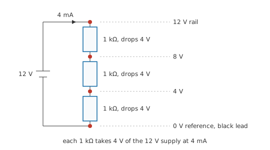
Now let the middle resistor fail open, its body cracked so that nothing can get through it. The same two probe positions give 12 V at the first junction and 0 V at the second. The supply reaches everything up to the break and goes no further, and past the break there is no current left to produce a drop across anything.
Locating the break took no more than that pair of readings: it lies between the last point still showing the supply and the first point showing nothing. Every technique below is a way of arriving at those two points quickly on a circuit that has rather more than three parts in it.
Practitioner
Halving the suspect region
A board with twenty parts between input and output offers twenty places for a fault to hide, and working through them in order is the slowest sequence available. Probe the middle instead. The half that reading condemns is where the fault is, and the other half never has to be looked at. Repeat on the survivor and the suspect region halves again at every probe, so sixteen stages are settled by four measurements.
Each of those measurements is a voltage measurement, taken with the circuit powered and nothing unsoldered. Voltage is the one quantity a meter collects without dismantling anything, and it is the quantity the design was specified in. Resistance tempts as an alternative and makes a poor opening move: it demands the power off, and with the part still fitted the meter sees every other path between the same two points alongside the one you aimed at.
The procedure
- Record the symptom and any readings already taken. Note what works, what does not, and what changed just before it stopped. A fault log costs a minute and is the only thing that will later tell you which of your own changes did what.
- Work out what the circuit ought to read. Expected node voltages come from the schematic and the parts on it rather than from the board in front of you.
- Prove the meter. Check it on a supply you know is live, so that a reading of zero means the circuit is dead and not the instrument.
- Check the supply at the point of use, under load — measured where the load is fed from, with the load connected and drawing its normal current.
- Set the meter to volts, put the black lead on the reference node, and leave it there. That leaves one hand free for probing and one range to keep track of.
- Measure at the midpoint of the chain and compare that reading against the expectation from step 2.
- Repeat on whichever half disagreed, halving again with each probe until one element or one joint is left.
- Measure across the suspect element, then from each of its ends to the reference. Each of those answers a different question.
- Confirm with a second, different kind of evidence before condemning anything — supply current, a known-good board, a warm component.
- Only now power down, lift one end of the part, and measure it alone. Out of circuit, a resistance reading finally means something.
- Change one thing, re-test the whole function, and write down what you changed. Change two things together and there is no saying afterwards which one mattered.
Step 2 is the one most often skipped, and it is what makes everything after it cheap. A run of resistances between a rail and the reference sets each junction by proportion:
and a known current through a known resistance predicts any drop you like:
Read backwards, that same relation turns a measured drop into the current that produced it, which is how a voltage reading across a resistor already in the circuit reports current with the loop left intact.
Worked example — A rail that is fine until something asks it for current
A logic board is fed from a bench supply set to 5.00 V, through a connector and a length of thin wire whose combined resistance comes to 0.15 Ω.
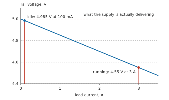
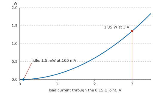
Idling, the board draws 100 mA. The feed drops 15 mV and the board sees 4.985 V, which reads healthy on any meter you are likely to be holding.
Bring it up to its working load of 3 A and the same resistance now takes 0.45 V. The board is fed 4.55 V, under the level its logic is guaranteed at, and it misbehaves in ways with no obvious connection to a connector.
Both readings were taken with the board intact, and between them they identify the culprit. Divide the fall in voltage by the rise in current and the answer is 0.15 Ω, which is the resistance sitting in the feed. A supply merely set too low would have read low at both currents, whereas a resistive joint gives itself away only while something is drawing.
What each kind of fault does to the drops
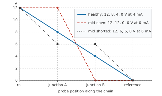
An open in a series path takes the whole supply across itself. No current flows anywhere in the path, so every other element is left with no drop at all: a healthy resistor either side of the break measures the same as a dead one, and the element carrying the supply across its own body is the one that failed. Open and short circuits sets out both conditions.
A short inverts that. The voltage across it collapses, and its share is pushed onto everything upstream. Short the middle resistor of the chain above and both junctions settle at 6 V, while the current climbs from 4 mA to 6 mA. The missing drop never turns up on its own: the supply current rises with it, past anything the circuit has business taking.
A partially open joint is the awkward one: a resistance where the design assumed there was none. Its drop is proportional to the current through it, so it stays out of sight at light load and takes over at heavy load. Such a joint is often warm to the touch, and the worked example above is exactly that fault. A dry solder joint, a corroded crimp, a displaced connector pin and an undersized conductor all present the same way, and wire resistance and voltage drop treats the healthy version of the same effect.
Across an element, or down to the reference
A meter reports one thing: the difference between the potentials at its two leads. With both leads on the ends of one component, you are asking how much of the supply that part takes. With the black lead on the reference and the red one anywhere you please, you are asking what potential that point sits at. Parking the black lead and walking the red one down a chain is the faster survey, and the across-measurement then confirms which single element owns the discrepancy.
A calculated expectation is one benchmark, and a working example of the same board is a better one, since it carries what the schematic leaves out: the drop in the wiring as built, the sag of the supply under load, and the spread of the parts actually fitted. With neither to hand, a circuit can often be compared against itself, because a stage duplicated for a second channel gives a pair of readings that ought to match, and the odd one out names the channel at fault.
Safety
Every measurement in this lesson is taken on a live circuit. That is the method being taught here, and it is why this notice is attached to it.
Use a meter and leads whose CAT rating covers the installation category you are working in, and scrap leads with damaged insulation instead of taping them. Probe with one hand where the layout allows it, keeping the other away from earthed metal, so that no path exists across your chest. Never place a meter in series with a mains circuit to read current: on a current range the instrument is close to a short circuit, and a clamp meter is the tool for that job.
Isolate and discharge stored energy before probing inside a power supply, a motor drive or anything carrying bulk capacitors. They hold a dangerous charge long after the supply is removed, and a failed bleed resistor leaves them charged indefinitely. Treat such a circuit as live until a meter has shown it at zero. The full working practice is set out in electrical safety fundamentals.
Going deeper
What the meter is really connected to
An in-circuit resistance reading describes the board
The probe tips define two nodes, and everything joining those nodes carries a share of the meter's test current. A resistor marked 10 kΩ with 2.2 kΩ of other paths across it — a second resistor, a winding, a return through a neighbouring stage — reads 1.8 kΩ, a value belonging to no component on the board. Read as a component value, that figure condemns a healthy part; all it actually describes is the board.
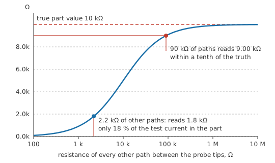
Semiconductors make the situation worse, since they are not resistances at all. A meter on its resistance ranges applies a small test voltage, and a junction forward-biased by that voltage conducts while the same junction reversed does not. Swap the leads and the reading changes, which is a genuine result about the junction and a worthless one about the resistor beside it. Boards also carry parallel paths no schematic shows: leakage across flux residue, a conductive contaminant, a via to a plane.
Removing the parallel paths is the only cure, and that means unsoldering one end of the part and lifting it clear. The cost is real — heat into the laminate, a pad at risk, a joint to remake — and it is why the measurement belongs at the end of the procedure rather than the start. In-circuit testing covers the techniques that extract useful results without lifting anything.
The meter joins the circuit while it is reading it
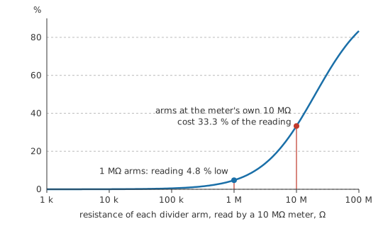
A voltmeter is a large resistance placed in parallel with whatever it measures, and on a high-impedance node it is not large enough to ignore. Two 1 MΩ resistors divide 10 V, so their junction should sit at 5.00 V.
Attach a meter of 10 MΩ input resistance and the lower arm becomes the parallel combination of the two, 909 kΩ. The divider has lost its symmetry, and the meter reports 4.76 V, low by 4.8 %. Both the circuit and the instrument are behaving properly, and the reading is a correct one for the circuit that exists while the probe is attached. Raise both arm resistances by a factor of ten and the error grows with them, which is the general case meter loading works through.
When one reading fits two faults
Voltage alone does not always separate the candidates. In a chain fed from a rail, an open in the element above a junction and a short from that junction to the reference both leave it reading zero. Supply current tells them apart at once — the open takes none, the short takes more than normal — and so does a resistance check once the suspect part has been lifted. A reading that fits both faults has still done its work by cutting the field down to a pair, and the next probe is the one chosen to separate them.
Where bisection stops working
Halving assumes a chain: a definite order of stages, one fault in it, and that fault present while you are looking. Feedback destroys the order, because a fault anywhere in a loop appears everywhere in the loop, and where the topology permits the cure is to open the loop deliberately. A shared rail costs you the independence instead, since one overloaded stage pulls the rail down and every other stage on it then reads wrong; that is why the supply check comes early.
A second fault present at the same time upsets the arithmetic, because a half declared good may be holding it. And an intermittent removes the premise altogether: readings taken while the circuit is behaving describe a circuit with nothing wrong with it. What works there is to leave a meter or a scope on the most suspect node and provoke the board — heat, cold, flex, vibration — until the reading moves.
Common mistakes
- "Nothing works, so I will start by checking resistances." With the power off and the parts still soldered in, a resistance reading is a reading of the board. Take voltages first, powered, and let them decide where a resistance check is worth its cost.
- A supply measured with nothing drawing from it. An open-circuit reading proves the regulator is alive and nothing more. Weak joints, tired cells and undersized wiring are all invisible until current flows.
- Replacing the part that measured strangely before establishing what its neighbours were doing. An element with the full supply across it is very often the innocent survivor of a break somewhere else in the chain.
- Probing between two arbitrary points and reading the answer as a node voltage. Decide before the probes land whether you are asking what a part drops or what a node sits at. Both readings are honest; only one answers your question.
- Changing two things at once. When the symptom disappears there is no way to say which change removed it, and no clean way back if it returns.
- Trusting a meter you have not proved. A blown internal fuse, a broken lead or a flat battery all produce zero volts on a live circuit, which is indistinguishable from the fault being hunted.
Frequently asked questions
Why measure voltage before resistance?
A voltage reading is taken with the circuit powered and intact, so it describes the circuit as it runs. Resistance needs the power off, and in circuit the meter measures every path between the probes at once — usually several parts in parallel with the one you meant to test.
What does a short circuit look like on a voltmeter?
You see almost no voltage across the shorted element, and more than expected across everything upstream of it. Supply current normally rises at the same moment, and that second symptom is worth capturing before anything is replaced.
An open and a short both give zero at the same node. How do I tell them apart?
Look at current instead of voltage. An open path takes none at all, while a short takes more than the circuit should draw. Lifting one end of the suspect part and measuring it on its own settles the question too, at the cost of a joint.
Is it safe to measure a circuit while it is powered?
On low-voltage battery and bench-supply work, yes, with ordinary care. On mains-connected equipment it is a specialised task needing rated leads, a rated meter, one-handed technique and a plan for stored energy. Much of that work can be done isolated instead.
The fault only shows up when the equipment is warm. What then?
Bisection assumes the fault is present while you probe, so the first job is to reproduce it deliberately: run the equipment to temperature, then take the readings. Where the fault comes and goes, leave a meter connected to the most suspect node and provoke the board while watching it.