

Quick Answer
Voltage drop is the voltage lost across a cable's own resistance when current flows through it, and it never reaches the load. It grows with conductor length and with current, and falls as cross-sectional area increases. On low-voltage systems it often settles the cable size before the current rating does.
Intuition
The wire is a component
Wires in a circuit are usually treated as nothing at all — perfect connections that carry current and take nothing in exchange. The assumption costs nothing on a small board, and it fails almost everywhere larger.
Wire is made of copper, and copper has resistivity. A metre of it has a small resistance, twenty metres has twenty times as much, and a thin conductor has more than a thick one. Push current through that resistance and — by exactly the same rule that governs every other resistance — a voltage appears across it. That voltage is subtracted from what the load receives, and it is called voltage drop.
The return conductor is the part people forget. Current goes out along one wire and comes back along the other, so the drop happens twice, and the length that matters is the round trip rather than the distance to the load.
How large the drop is in volts also says less than it appears to. What decides whether it matters is the fraction of the supply it represents: one volt is invisible on a mains circuit and catastrophic on a 5 V supply. Low-voltage systems — vehicle wiring, solar installations, battery equipment, USB — are where this problem lives, because the same amount of copper takes the same volts out of a much smaller total.
The symptoms are already familiar. Headlights dim when a winch runs, a phone charges slowly on a long thin cable and quickly on a short thick one, and an LED strip is visibly dimmer at its far end. In each case the equipment is sound, and the cable is taking a share of the voltage for itself.
Practitioner
Working out the drop
The conductor's resistance comes from its material and its dimensions, and the voltage across it then follows from the current through it.
Worked example — A 12 V circuit at the end of a long cable
A load draws 10 A from a 12 V supply through copper of 2.5 mm², over a round-trip conductor length of 20 m. Copper's resistivity is 16.8 mΩ·mm²/m.
The cable's resistance works out at 134 mΩ, and multiplying by the current gives the drop along it: 1.34 V.
The load therefore receives 10.66 V rather than the nominal figure, which is 11.2 % of the supply gone. The cable also dissipates 13.4 W as heat along its length: energy the load never gets, and warmth the installation has to shed.
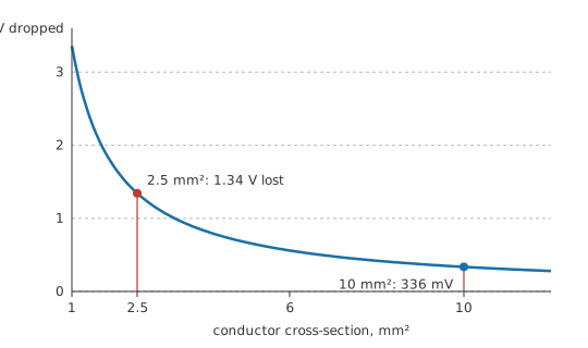
A cable's current rating answers a different question from its drop. The rating is a thermal limit, describing how much current the conductor can carry without cooking its insulation. Voltage drop is a performance limit, and on a long low-voltage run it is the one that bites first — the cable sits well inside its thermal rating while the load misbehaves. Sizing on the current rating alone is the standard way to get this wrong.
Of the quantities that set the drop, most are handed to you. The current belongs to the load, and the length to wherever the two ends happen to be. That leaves cross-section, where a bigger conductor buys less drop in direct proportion, and system voltage, which is a design decision made early or not at all.
Cross-section is an expensive handle to pull. Resistance is inversely proportional to area, so halving the drop means doubling the copper, and cable cost, weight, bend radius and terminal size all move with it. Conductor sizing ends up an economic decision as much as an electrical one. Wire and cable covers the practical tables.
Whatever the conductor drops, it dissipates. Every volt lost along a cable is power turned into heat inside that cable, and on a long high-current run it comes to a substantial fraction of what the supply delivers.
Engineer
Sizing to a budget
In practice the limit is set before the calculation is done. Installation practice commonly restricts drop to a few percent of nominal voltage, and equipment specifications often demand something tighter; the conductor is then sized to meet whichever figure applies.
Worked example — What conductor a 3 % budget needs
Keep the same 10 A load on the same 20 m round trip, and allow a drop of 3 % of the 12 V supply — that is 360 mV.
Dividing that permitted drop by the load current gives the largest acceptable cable resistance: 36 mΩ. Rearranging the resistivity relationship for area gives the conductor needed: 9.33 mm².
Cable is not made in arbitrary sizes, so the next standard size up is 10 mm², giving 33.6 mΩ and an actual drop of 336 mV, comfortably inside budget. The conductor in the first example was four times too small for this job, while being entirely adequate for the current on thermal grounds.
Copper's resistance is only fixed at a fixed temperature. It rises with temperature by roughly four parts in a thousand per degree, and the drop is what does the heating. A conductor sized at 20 °C and then run warm has more resistance, more drop and more heating than the calculation says — a small feedback loop that converges, but which leaves room-temperature figures optimistic. Cable derating for grouped, buried or insulated installations exists for the same reason.
Current crowds towards a conductor's surface as frequency rises, so on AC the effective resistance sits above the DC value — negligible at mains frequency for small conductors, significant for large ones. The cable's inductance then contributes a reactive drop that adds to the resistive one at an angle, so on long AC runs with a poor power factor the total exceeds what a resistance-only calculation predicts.
Every joint counts as part of the conductor. A crimp, a screw terminal, a connector pin or a solder joint each add resistance in series with the cable, and one that has degraded can exceed the whole run on its own. Joint resistance also climbs as the joint heats, which raises its dissipation again — the runaway described in open and short circuits. Measuring the voltage drop across a joint under load is among the fastest diagnostics available.
Drop in the return conductor causes trouble of a different kind. The return path's drop shifts the reference that everything downstream is measured against, which is exactly the mechanism in ground and reference points. A supply that is one volt low is inconvenient; a ground that is one volt high corrupts every measurement referenced to it.
Professional
Where the decision gets made
System voltage moves the drop further than anything else, and it is settled before any cable is chosen. The same cable carrying the same current on a mains circuit drops just 0.58 % of 230 V, against the 11.2 % it costs on the 12 V system. The absolute drop has not moved at all; only the denominator has.
A good deal of electrical practice follows from that comparison. The grid transmits at hundreds of kilovolts, data-centre and telecom racks moved from 12 V to 48 V distribution, electric vehicles run a high-voltage traction system alongside a low-voltage accessory bus, and solar arrays are wired in long series strings. Raising the voltage for a given power lowers the current, and drop and loss both follow the current.
Remote sensing attacks the problem at the regulator rather than at the cable. A pair of extra, current-free wires carries the supply's feedback input to the load terminals themselves, so the regulator measures what the load actually receives and raises its output to make up the difference. Bench supplies do this as standard, as does any board with a long distribution path — it is the four-terminal idea behind a Kelvin resistance measurement, applied to power rather than to metrology.
How the distribution is arranged decides which load suffers. A daisy chain hands the last load the accumulated drop of every segment ahead of it, which is why the far end of an LED strip is dim and the last socket on a chain is the weakest. A star arrangement gives every load its own path from a common point, leaving their drops independent of each other. Choosing between them comes down to whether the loads have to be equal or merely adequate.
Boards run into the same arithmetic on a smaller scale. A power plane, a track or a via has resistance, and a modern core rail may sit under a volt with tens of amperes flowing — conditions in which a few milliohms of copper eats a meaningful part of the whole tolerance budget. The calculation does not change; only the units do, and the decision becomes one about copper weight and plane geometry.
Drop is a measurement to take with the load running. Read the voltage at the source and at the load at the same moment, while the load is drawing its normal current, and take the difference. A resistance measurement on a disconnected cable will miss joints that only misbehave under load, along with the temperature rise and the connector degradation that appear once current flows.
The drop budget is shared out among everything in the path. Supply regulation, cable drop, connector drops, fuse-holder and switch-contact resistance and the load's own tolerance all draw on the same allowance. Budgeting the cable alone and meeting the rest afterwards is how a design that calculates correctly still fails at the end of a long harness.
Common mistakes
- Sizing a cable on its current rating alone — that is a thermal limit. On long, low-voltage runs the voltage drop is the binding constraint and needs a much larger conductor.
- Using the one-way distance — current flows out and back, so the resistance that matters is that of the round trip.
- Judging a drop in volts rather than as a fraction — one volt is trivial at 230 V and ruinous at 5 V. The percentage is what matters.
- Ignoring joints and connectors — a degraded crimp or terminal can add more resistance than the entire cable, and it worsens as it heats.
- Calculating at room temperature only — copper's resistance rises with temperature, and the drop itself does the heating.
- Budgeting the cable and forgetting everything else — supply regulation, contacts, fuses and the load's own tolerance all draw on the same allowance.
Frequently asked questions
What is voltage drop in a cable?
The voltage that appears across the cable's own resistance when current flows through it. It is subtracted from what the load receives, and it grows with length and current and falls with cross-section.
Why does the return conductor count?
Because the current flows out along one conductor and back along the other, developing a drop in both. The resistance that matters is that of the complete round trip.
How do I choose a cable size for a given voltage drop?
Decide the permitted drop, divide it by the load current to get the maximum acceptable cable resistance, then use the resistivity relationship to find the cross-section that gives it — and take the next standard size up.
Why is voltage drop worse on low-voltage systems?
Because the same absolute drop is a much larger fraction of a smaller supply voltage, and because delivering the same power at a lower voltage requires proportionally more current, which increases the drop as well.
What is remote sensing?
Running separate, current-free wires from a supply's feedback input to the load terminals, so the regulator measures and corrects for the drop in the distribution cable rather than ignoring it.