

Quick Answer
Resistivity is a property of a material: how strongly a standard shape of it opposes current, measured in ohm-metres. Resistance belongs to a particular object and depends on its shape as well as its material. Conductance is the reciprocal of resistance, measured in siemens.
Intuition
Wool is warm; the jumper is warm
"Wool is warm" and "this jumper is warm" are two different kinds of statement. One is about a material, and it holds for every piece of wool that ever existed. The other is about a single object, and it depends on how thick that jumper is, how it is knitted and whether it has sleeves. Both are true, and mixing them up produces nonsense: a wool sock is not as warm as a wool coat, and that is a fact about socks rather than about wool.
Electricity draws exactly the same distinction. Resistivity is the material statement. It says how strongly a given substance opposes current, whatever quantity of it you have and whatever shape that quantity is in. Copper has one resistivity, aluminium another, silicon another again, and none of those figures moves when the piece changes size.
Resistance is the object statement. It belongs to a particular wire, track or component, and it depends on the material and on the geometry: longer means more, thicker means less. A hair-thin copper wire and a copper busbar are made of equally good copper and have wildly different resistances.
Getting from one to the other takes only a short calculation, which is what makes the pair so useful: it puts a number on the resistance of something that has not been built yet, out of a figure in a materials table and a few dimensions on a drawing.
Conductance is resistance turned upside down: how easily current gets through, rather than how hard it is opposed. The two carry the same information. Where paths run side by side, though, the upside-down version is a great deal easier to think in, and that case comes up constantly.
Practitioner
From material to object, and back
The link between resistivity and resistance is geometry: length increases resistance, cross-sectional area reduces it.
Resistivity is written with the Greek letter ρ and quoted in ohm-metres in SI. Cable work uses an equivalent form, ohm-millimetre-squared per metre, because it lets a run in metres and a cross-section in square millimetres go straight in — the units every cable table is written in.
Worked example — What a real cable run costs you
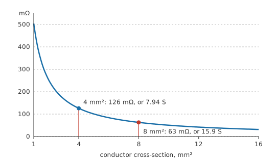
A run of 30 m of copper cable with a cross-section of 4 mm² carries current to a load. Copper's resistivity is 16.8 mΩ·mm²/m.
Multiplying resistivity by length and dividing by area gives the resistance of the run: 126 mΩ.
Turned upside down, that same run has a conductance of 7.94 S, the number that says how much current it will pass per volt across it.
The reciprocal relationship is the definition of conductance, and its unit is the siemens:
The reciprocal view comes into its own when paths run in parallel. Two conductors side by side offer the sum of their conductances, as directly as two resistances in series offer the sum of their resistances. Anything that adds when you put things side by side — cross-sectional area, current capacity, conductance — is telling you it belongs to the parallel case.
Conductivity, written σ, is the material version of conductance, and it is simply the reciprocal of resistivity. Materials scientists tend to quote conductivity and electrical engineers resistivity; the two carry identical information.
Every published resistivity comes attached to a temperature, and that temperature is almost always 20 °C. Copper's figure moves by a noticeable fraction of a percent per degree — enough that a hot cable and a cold one are meaningfully different, as temperature effects on resistance sets out.
These figures get used constantly: sizing a cable for an acceptable voltage drop, choosing a track width on a board, working out how much a shunt will heat, deciding whether aluminium can replace copper in a given space. Each is the same calculation with a different unknown moved to the left. Wire and cable collects the practical tables.
Engineer
Why the geometry enters the way it does
The length term and the area term come from different arguments, and each one can be seen directly once it is taken on its own.
Length appears because a longer conductor is more resistances in series. Cut a wire into ten equal pieces and each has a tenth of the resistance; reassembling them in series recovers the original. Area appears because a thicker conductor is more paths in parallel. Two identical wires side by side have twice the area and half the resistance, because each carries half the current for the same voltage.
Worked example — Doubling the copper
Take the same 30 m run and double its cross-section to 8 mm².
Its resistance halves, to 63 mΩ, and its conductance doubles, to 15.9 S, from the 7.94 S of the thinner run.
Doubling the cross-section and running two of the thinner cables in parallel give exactly the same answer, and for the same reason: conductances add in parallel. Written in resistances that case needs reciprocals and looks awkward, while written in conductances it is addition.
Underneath the geometry, the microscopic content is a statement about the material alone. The current density in a conductor is proportional to the electric field driving it, with conductivity as the constant of proportionality — the point-by-point form of Ohm's law. Integrate that over a uniform bar and the length-over-area relationship falls out, with resistivity appearing as the material constant. Resistivity is therefore the quantity the physics actually contains, and resistance is what a particular geometry makes of it.
The formula assumes a uniform cross-section, and says nothing about what to do when the shape changes along the way. A tapering conductor, a via, a solder joint or a bond wire has to be integrated along its length, or broken into sections and treated as a series chain.
It assumes a uniform current distribution as well, which holds at DC and stops holding as the frequency rises. Current crowds towards the surface — the skin effect — so the effective area falls and the effective resistance rises, while the material and the geometry stay exactly as they were. Above the frequency where this sets in, the DC calculation understates the loss, sometimes by a large factor. The same crowding happens at a corner or a constriction even at DC.
And it treats the conductor as one material. A plated or clad conductor is two materials in parallel, and a composite such as copper-clad steel behaves as copper at high frequency, where the current runs in the cladding, and as something much worse at DC, where it does not.
A uniform thin layer collapses the geometry further still. On a PCB copper layer, a thin-film resistor or a doped semiconductor region the thickness is fixed by the process, so resistance depends only on the ratio of length to width. That ratio is counted in squares, and the material is characterised by its sheet resistance: its resistance per square. Thinking in squares is a genuinely different way of handling geometry, and it is how every thin-film and integrated resistor is designed.
Professional
What the material figure leaves out
Conductor materials get compared on a percentage scale. The International Annealed Copper Standard defines a reference conductivity, and other conductors are quoted as a percentage of it — annealed copper is 100 % IACS by definition, and aluminium comes in around 61 %. That single number tells a designer immediately how much extra cross-section an alternative material needs, which is usually the decision being made.
On a board the working unit is sheet resistance. One-ounce copper is about 0.5 mΩ per square, so a track can be costed by counting squares along it.
A track 50 squares long therefore contributes 25 mΩ — small until it is carrying amperes, or until it is in the return path of a sensitive measurement. Every trace-width decision comes out of that calculation, and it is done in squares rather than in millimetres precisely because the thickness is not a variable the designer controls.
Temperature belongs in the specification rather than in a correction applied afterwards. A cable sized at 20 °C and run hot has meaningfully more resistance, which increases the drop, which increases the heating. In current-sense and precision-divider work the same effect appears as drift, and the material is chosen for a low temperature coefficient rather than for a low resistivity — which is exactly why precision shunts are made from manganin or similar alloys rather than from copper.
Then there are the joints, which often dominate everything else. A perfectly calculated conductor delivered through an oxidised terminal, a marginal crimp or a cold solder joint gives a resistance the calculation never contained. In low-resistance systems the loss and the ageing usually live in the terminations rather than in the conductors.
Plating and cladding are conductivity decisions taken for chemical reasons. Tin, silver and gold plating exist to control oxidation and contact behaviour, not to improve bulk conductivity. At high frequency, though, they become the conductor, and a poorly chosen plating on a signal conductor is a loss mechanism that no DC measurement will reveal.
In semiconductors, doping makes resistivity a design variable, set deliberately over many orders of magnitude, so wafer resistivity is a process specification rather than a material constant. Layer 1's rule needs refining to accommodate that: resistivity is still fixed for a given material sample, and still independent of the size and shape of the piece, but in a semiconductor the material itself is engineered, so two wafers of what a chemist would call the same substance can differ in resistivity by a factor of thousands. See semiconductor materials. The same relationship is therefore a manufacturing parameter in one industry and a table lookup in another.
Common mistakes
- Using resistivity and resistance interchangeably — resistivity belongs to the material and never changes with size; resistance belongs to the object and depends on its dimensions.
- Forgetting that published resistivity is a 20 °C figure — a hot conductor has noticeably more resistance, and the drop it causes heats it further.
- Applying the DC relationship at high frequency — current crowds towards the surface, the effective area shrinks, and the real resistance is higher than the calculation says.
- Treating a plated or clad conductor as one material — it is two in parallel, and which one dominates depends on frequency.
- Working in resistances when the paths are parallel — conductances add directly and resistances do not. The reciprocal view exists to make exactly this case easy.
- Sizing a conductor and ignoring the joints — terminations, crimps and contacts frequently contribute more resistance than the conductor they join.
Frequently asked questions
What is the difference between resistivity and resistance?
Resistivity is a property of a material, independent of size or shape. Resistance is a property of a specific object, and depends on the material's resistivity together with the object's length and cross-sectional area.
What is conductance measured in?
Siemens, symbol S. One siemens is the conductance of something with a resistance of one ohm, since conductance is the reciprocal of resistance.
Why does a thicker wire have less resistance?
More cross-section means more parallel paths for the current, so each carries a smaller share for the same voltage. Doubling the area halves the resistance.
When is conductance more useful than resistance?
Whenever paths are in parallel. Conductances add directly for parallel elements, while resistances require reciprocals, so the algebra is much shorter in conductance.
What is sheet resistance?
The resistance per square of a uniform thin layer. Because the thickness is fixed by the process, resistance depends only on the length-to-width ratio, so geometry reduces to a count of squares.
Knowledge check
A 30 m run of 4 mm² copper cable, with copper at 16.8 mΩ·mm²/m — what is its resistance and its conductance? (Show answer)
The same run is made in 8 mm² cable instead. What changes? (Show answer)
A track on one-ounce copper is 50 squares long, at about 0.5 mΩ per square. What resistance does it add? (Show answer)
Does a thick copper busbar have a lower resistivity than a thin copper wire? (Show answer)
Why does the DC resistivity calculation understate a conductor's resistance at high frequency? (Show answer)
References
- CRC Press, CRC Handbook of Chemistry and Physics — electrical resistivity of the elements at 20 °C, the source of the copper figure used here.
- IEC 60028, International standard of resistance for copper — the annealed-copper reference behind percentage IACS conductivity figures.