

Quick Answer
Resistance is the measure of how strongly a component opposes the flow of electric current. Its SI unit is the ohm, symbol Ω, and one ohm is one volt of potential difference per ampere of current. A larger resistance means less current flows for the same applied voltage.
Intuition
Friction, for charge
Slide a book across a table and it stops. Slide it across ice and it travels much further. The push you gave it was the same; what differed was how hard the surface fought back. Friction takes energy out of the motion and turns it into heat, quietly, all the way along.
Resistance is the same story told about charge. Push charge through a path and something in the material opposes the motion, takes energy out of it, and releases that energy as heat. A path with high resistance fights hard, so little current gets through for a given push. Where resistance is low, the charge is barely fought at all.
Its unit is the ohm, written with the Greek letter Ω. One ohm is the resistance that lets one ampere flow when one volt is applied. The everyday range is enormous: a metre of thick cable is a fraction of an ohm, a small heater a few tens, a signal resistor thousands, the surface of a plastic case millions of millions.
That opposition is where electrical energy turns into heat, a nuisance in a cable and the entire point of a kettle. It is also the handle for controlling current on purpose, which is why a small component called a resistor sits in almost every circuit ever built. Resistance is rarely wanted for itself; what makes the part indispensable is that a known amount of it is cheap and stays put.
The friction picture carries most of the way and then stops. Friction depends on how hard you press; resistance, for ordinary materials at a steady temperature, is the same whatever the push behind it. That constancy is a surprising property, and it has limits, but where it holds a circuit becomes predictable.
Practitioner
Getting a number for it
Resistance is defined as a ratio: the voltage across something divided by the current through it. That is the working content of Ohm's law, read as a definition rather than a prediction:
Any unknown resistance therefore falls out of two multimeter readings, and the meter's own resistance range works this way internally: it pushes a known small current through the unknown and measures the resulting voltage.
Worked example — Finding an unknown resistance
A component has 5 V across it and passes 20 mA.
Dividing voltage by current gives its resistance: 250 Ω. Multiplying voltage by current gives what it is dissipating as heat: 100 mW. The first number says how the circuit behaves; the second decides whether the component survives its own dissipation.
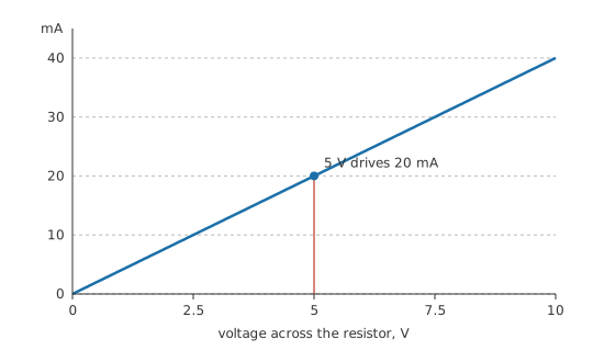
A resistance range only works on a circuit that is switched off, because the meter supplies its own test current; on a live circuit it reads nonsense and may be damaged. Isolation matters too: a resistor soldered in parallel with other parts measures the combination, not itself, which is why one leg usually has to be lifted.
The value comes from shape and substance together. A longer path has more resistance, a thicker one less, and the material's own resistivity scales whatever the geometry gives. A long extension lead therefore drops more voltage than a short one of the same gauge.
Heat deserves the same attention as current. Every ohm carrying current makes some, and a resistor's power rating is easy to exceed without noticing. Power can be written from voltage and current, from current and resistance, or from voltage and resistance — one statement arranged for whichever pair you happen to know:
Values cluster by application. Contacts, shunts and cable sit down in the milliohms; heaters, motor windings and speaker coils land between an ohm and a few tens. Ordinary circuit design works from the hundreds up to the hundreds of thousands, and bias networks, insulation and meter inputs run into megohms. A resistance out of place for the job it is doing usually points at a mistake somewhere.
Engineer
Where it comes from, and how to measure it honestly
At the microscopic level, resistance is what happens when carriers moving through a solid keep colliding with something. Applying a field accelerates the conduction electrons, and lattice vibrations, impurity atoms and defects repeatedly scatter them, so the motion settles to a steady average drift rather than accelerating without limit. The energy the field supplies between collisions is handed to the lattice at each one, which is heat. Resistance is therefore a continuous conversion of ordered motion into disordered motion rather than a barrier the charge pushes past.
Temperature enters through the scattering rate: a lattice vibrating harder scatters carriers more often, so metals grow more resistive as they heat — the subject of temperature effects on resistance. Linearity has a different origin. The number of carriers in a metal barely changes with the applied field, so the drift stays proportional to the field, and that proportionality is what lets resistance be quoted as a single constant.
That constancy has limits the earlier layers glossed over. In a diode, a lamp filament or a thermistor under self-heating, the ratio V/I is different at every operating point, so quoting "the resistance" of such a part means nothing without saying where. For small changes around a chosen operating point, engineers use the local slope instead — the dynamic resistance — and treat the device as linear only within the region where that slope is roughly constant.
Measurement has limits of its own, and they bite hardest at the bottom of the range, where the leads count for as much as the part.
Worked example — Why low resistances need four wires
A current-sense shunt of 100 mΩ is measured with an ordinary two-lead meter whose test leads and contacts contribute 100 mΩ between them.
The meter cannot tell the two apart, because they sit in series with each other in the path it is measuring. It reports the sum: 200 mΩ, an error of 100 %.
Separating the current path from the voltage path removes it. A four-wire, or Kelvin, connection forces the test current through one pair of leads and senses the voltage with a second pair carrying almost none, so the lead resistance drops out. Every precision measurement of a low resistance works this way, and current-sense resistors are built with four terminals for the same reason.
At the other extreme, a very high resistance is corrupted by the meter's own input resistance sitting in parallel with it, and by surface leakage across the board, the fixture and the operator's fingerprints. At either end of the range, a trustworthy number takes more than reading a display.
Dissimilar metals in a test setup add a thermoelectric voltage of their own, small but landing directly on top of a low-resistance measurement, which is why precision measurements reverse the test current and average the results.
Professional
The number on the part is a band
A resistor is a specification with a number printed on it. Marked value, tolerance, temperature coefficient, power rating, voltage rating and stability over life are six independent figures, and a design that checks only the printed one is relying on luck.
A nominal 1 kΩ part at 5 % tolerance is guaranteed only to lie between 950 Ω and 1.05 kΩ at room temperature when new. Where the design needs a ratio rather than an absolute value — a divider, a gain-setting pair — matched parts from the same batch behave far better than the tolerance alone suggests. Where it needs an absolute value, the tolerance is the only guarantee there is. Resistor tolerance and the E-series of preferred values explain why the available values are spaced the way they are.
A part rated for a given dissipation in free air at 70 °C is rated for less inside a closed box, less again standing next to another hot part, and less again on a board with no copper to spread the heat. The rating is quoted at a temperature and falls away above it, and resistor power rating and power dissipation cover the derating properly. Pulse handling is a separate specification again, since a part can survive energies far above its continuous rating for microseconds and fail at a fraction of it for seconds.
Every resistor is also a small inductor and a small capacitor. A wirewound part is a coil, so its impedance rises with frequency, and any part has end-to-end capacitance that eventually shorts it out. Between those two effects a resistor behaves as a resistor only over a band, and the band narrows as the value moves away from the middle hundreds of ohms. In RF and in fast digital work, that band is one of the things a part gets selected on.
High values drift for reasons that never trouble low ones. Voltage coefficient — a slight dependence of resistance on the voltage across it — matters in high-value, high-voltage dividers, and moisture ingress and surface contamination move the measured value over years. Thick-film parts are cheap and stable enough for almost everything; thin-film and metal-foil parts exist because "almost everything" excludes precision analog.
How a resistor fails depends on how it was overloaded. Film parts driven past their rating usually go open, the benign outcome. Under a surge some go short first, so a resistor used as a fuse or a safety element must be a type qualified for it. Resistor failure modes and resistor selection carry this further.
Some parts carry a resistance that is meant to move. A thermistor's resistance is the signal, a varistor's collapses deliberately above a threshold, and a potentiometer's is adjustable by design; in each of them the variability is the feature rather than the fault.
Common mistakes
- Measuring resistance in a live circuit — the meter applies its own test current and reads the circuit's voltages instead. Power down and isolate at least one leg first.
- Ignoring lead and contact resistance — at the milliohm level the leads dominate. Use a four-wire connection or accept an error that can exceed the quantity being measured.
- Quoting a single resistance for a non-linear part — a diode, lamp or self-heated thermistor has a different V/I ratio at every point. State the operating point or use the local slope.
- Designing to the marked value — tolerance, temperature coefficient and ageing all move it. Check whether the circuit needs an absolute value or only a ratio.
- Sizing a resistor by value alone — the dissipation decides survival. Work out the power and compare it against the rating at the temperature the part will actually see.
- Assuming resistance is frequency-independent — leads add inductance, the body adds capacitance, and above some frequency the part stops behaving as a resistor.
Frequently asked questions
What is resistance in simple terms?
It is how strongly something opposes electric current. One ohm allows one ampere to flow for each volt applied, and higher resistance means less current for the same voltage.
What causes resistance in a material?
Carriers moving through the material are repeatedly scattered by lattice vibrations, impurities and defects. Each collision transfers energy to the material as heat, which is why resistance and heating always go together.
How do I measure the resistance of a component?
Isolate it from the circuit, power the circuit down, and use a multimeter's resistance range. For values below about an ohm, use a four-wire connection so the test leads are not included.
Why does a thick wire have less resistance than a thin one?
More cross-section means more parallel paths for the same current, so each carries less and the total opposition falls. Resistance is proportional to length and inversely proportional to area.
Is resistance always constant?
No. It is constant for ohmic materials at a fixed temperature. Diodes, lamps, thermistors and anything that heats up under its own dissipation have a resistance that depends on the operating point.