

Quick Answer
Electric current is the rate at which electric charge flows past a point in a circuit. Its SI unit is the ampere, and one ampere means one coulomb of charge passing every second. Current is given the symbol I, and in a simple series loop it is the same at every point.
Intuition
Flow, not pressure
Charge that stays where it is does nothing useful. Once it moves you have current — and it is the current that lights the lamp and spins the motor.
The word to hold onto is rate. Current is not an amount of electricity; it is how fast electricity is going past. Think of a river. The amount of water is one thing; the flow rate — how many litres go past each second — is another. Current is the flow rate. Its unit, the ampere (usually just "amp", symbol A), means one coulomb of charge going past every second.
What catches people out first is that the current is the same all the way round a simple loop. Connect a battery to a lamp with two wires and exactly as much current flows in the returning wire as in the outgoing one. The lamp takes energy out of the charge passing through it and leaves the charge itself alone. Water in a closed central-heating loop behaves the same way: the radiator takes heat out of the water, not water out of the loop.
The spread of the everyday numbers surprises people too. A digital watch runs on millionths of an ampere and an LED wants a few hundredths, while a kettle takes about ten and a car starter motor pulls hundreds for a second or two. All of those are the same quantity at wildly different scales — which is why prefixes matter so much here.
Practitioner
Working with amperes
Current is the charge that passes a point divided by the time it takes to pass. The same relationship is more often written the other way round, as charge equals current multiplied by time:
Read for current, it gives charge divided by time. That is a definition rather than a result derived from anything else.
Worked example — Average current from charge moved
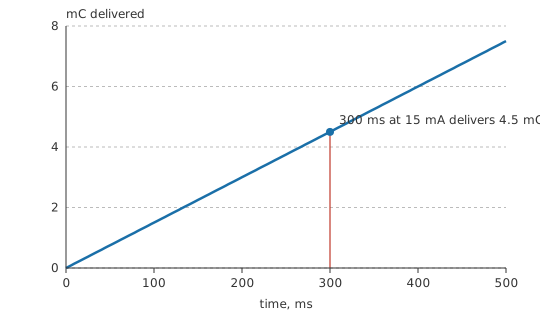
A capacitor gives up 4.5 mC of charge while discharging into a load, and takes 300 ms to do it.
Dividing charge by time gives the average current over that interval: 15 mA. "Average" is doing real work in that sentence — the instantaneous current at the start of a capacitor discharge is much higher than at the end, and this single number says nothing about the shape.
Magnitudes worth memorising, because they let you spot a wrong answer instantly:
| Current | Typical source |
|---|---|
| nA to µA | sleeping microcontroller, op-amp input bias, leakage |
| 1–20 mA | indicator LED, logic input, small sensor |
| 100 mA – 2 A | USB port, microcontroller board, small motor |
| 5–15 A | kettle, heater, power tool on a domestic outlet |
| 100 A and up | car starter, welder, motor inrush |
Current is the awkward quantity to measure. Voltage is measured across a component, with the meter connected in parallel and barely disturbing anything. Current must be measured through the circuit, so the circuit has to be broken and the multimeter inserted in series. A current-measuring meter is deliberately near-zero resistance; connect one across a supply by mistake and you have made a short circuit, which is why meters have a separate fused current jack and why that fuse is the most frequently replaced part in any workshop.
Where breaking the circuit is impractical or unsafe, a clamp meter measures the magnetic field around the conductor instead and never touches the circuit at all. On a board, the usual method is a small current-sense resistor whose voltage drop is proportional to the current through it.
Safety
Never place a multimeter in series with mains wiring, and never connect a meter set to a current range across a supply of any kind. Both mistakes put the full source current through a low-resistance path inside the meter. On a battery bench this destroys a fuse; on mains it can produce an arc flash. Use a clamp meter for mains currents, and check the meter's CAT rating before it goes anywhere near an installation. General practice is covered in Electrical Safety Fundamentals.
A current does not set its own value. The voltage applied and the resistance of the path fix it between them — a relationship formalised in Ohm's law. Components that would otherwise draw too much — LEDs above all — need deliberate current limiting.
Engineer
What is actually moving, and how fast
At the microscopic level, current in a metal is a drift superimposed on chaos. The conduction electrons are already moving at enormous speed in random directions; applying a field adds a small systematic bias to that motion. The net drift is astonishingly slow — well under a millimetre per second for ordinary currents in ordinary wire — yet a lamp lights the instant the switch closes, because the electromagnetic field that sets every electron in the wire moving propagates at a substantial fraction of the speed of light. The electrons do not have to travel from the switch to the lamp; the ones already in the lamp start moving immediately.
Signal timing therefore depends on field propagation and on the geometry of the conductors rather than on how fast the carriers themselves go. The same reasoning explains why current is a property of a path, not of a wire: at high frequencies the return current does not spread out through a ground plane but crowds under the outgoing trace, because that is the lowest-inductance loop available.
Current density — current divided by cross-sectional area — is often the more physical quantity than current itself, since it is density that determines heating and electromigration. That is why a conductor's rating depends on its cross-section, and why the same current is trivial in a busbar and destructive in a bond wire. See wire and cable.
Charge conservation gives current its most useful structural property: charge cannot pile up at a junction, so the currents arriving at any node must sum to the currents leaving it. That is Kirchhoff's current law, and it is the reason the current is identical everywhere in a series loop.
Conventional current flows from the positive terminal, through the external circuit, to the negative — a definition fixed before the electron was discovered. In a metal the actual carriers, being negative, drift the opposite way. Schematics, datasheets and the equations on this site all use the conventional direction, and an answer worked out that way needs no correction; what disagrees with the electrons is the physical picture, not the arithmetic. Conventional vs electron flow has the detail. Note also that in electrolytes and in plasmas both signs of carrier move, in opposite directions, and both contribute to the same current.
Used without a qualifier, "current" usually means a steady direct current. Once the current alternates, a single number is ambiguous: peak, average and RMS are all different, and it is the RMS value that determines heating. Even a nominally DC supply is rarely steady.
Worked example — A pulsed load and the current that really matters
A wireless sensor node draws 200 mA while its radio transmits, for 5 ms in each cycle. Multiplying current by time gives the charge moved in one burst: 1 mC.
The node repeats that burst every 100 ms, and sleeps in between. Dividing the charge per cycle by the cycle time gives the average current: 10 mA.
Each number does a separate job. Battery life follows the average, while the peak decides the supply's output impedance, the decoupling, and whether the rail collapses when the radio keys up: a cell that comfortably supplies the average may not supply the peak at all.
Professional
Rating, sensing and the currents that are not on the schematic
What limits a conductor is heat, not any term in the equations. A wire, connector or PCB trace carries current until the temperature rise becomes unacceptable, and the acceptable rise is a design decision rather than a property of the copper. IPC-2221 gives the classic trace-width curves for internal and external layers at a chosen temperature rise, and every one of them is a starting point to be derated for ambient temperature, adjacent copper, conformal coating and airflow. Connectors are rated per contact, and they derate hard when several adjacent contacts carry current at once.
Peak, average and RMS are three different specifications. Heating follows the RMS value, survival under a surge follows the I²t integral, and regulator or battery limits are usually quoted as an average with a separate peak allowance and a time limit. Quoting one where another is meant is a common cause of parts that pass a bench test and fail in the field. Fuses are specified in exactly these terms, and their I²t rating must be coordinated with what the protected device can survive.
Inrush is a separate design problem from steady state. Capacitor charging, incandescent filaments, motors and transformers all draw many times their running current at switch-on, for a period short enough to be invisible on a slow meter and long enough to weld a relay contact, nuisance-trip a breaker or exceed a supply's current limit. Inrush limiting — NTC thermistors, soft-start, pre-charge resistors — is sized during the power design itself, alongside the steady-state rating.
Which sensing method to use depends on which constraint binds. A shunt resistor is cheap, accurate and linear, but is galvanically connected and dissipates power; low-side placement is simplest but corrupts the ground reference, and high-side placement needs an amplifier that tolerates the common-mode voltage. Hall-effect and fluxgate sensors give isolation and handle large currents with no insertion loss, at the cost of offset drift. Current transformers work only for AC. In every case the sense element's parasitic inductance matters for fast edges, which is why four-terminal shunts exist.
Some currents never reach the schematic and turn up in the field anyway: leakage through contaminated board surfaces, quiescent current in every regulator and pull-up in a battery product, ground-loop currents driven by potential differences between grounds, and capacitively coupled currents through interwinding capacitance in a supply. In battery-powered work the quiescent current budget deserves the same discipline as the active one: a microampere of permanent drain is milliampere-hours per month.
Every current also produces a magnetic field — the basis of some components and a nuisance around others. It is what makes clamp meters, motors and transformers work, and it is what couples a switching supply's loop current into a nearby signal trace. See magnetic fields.
Common mistakes
- Thinking current is used up by a component — the current leaving a resistor equals the current entering it. What the component consumes is energy.
- Leaving a meter on a current range and probing a voltage — the meter is a near short circuit on that range. This blows the internal fuse at best and is genuinely dangerous on mains.
- Designing to average current when the peak sets the constraint — pulsed loads drain the battery at the average and collapse the rail at the peak, so a design has to satisfy both.
- Using a DC current rating for an AC or pulsed waveform — heating follows the RMS value, and fuse survival follows I²t; a peak figure alone tells you neither.
- Assuming return current spreads out over a ground plane — once the frequency is high enough that loop inductance rather than resistance decides the path, the return crowds under the outgoing trace, and the loop area left over is what radiates. Where that crossover sits depends on the geometry, so it is a question to answer for your stack-up, not from a remembered number.
Frequently asked questions
What is electric current in simple terms?
It is the rate at which electric charge flows past a point. One ampere means one coulomb of charge going by every second.
Is current the same everywhere in a series circuit?
Yes. Charge cannot accumulate anywhere in the loop, so every component in a single series path carries exactly the same current.
Why must an ammeter be connected in series?
Because it measures what passes through it. A current meter is built to have almost no resistance, so connecting it across a supply instead of in the path creates a short circuit.
How fast do electrons actually move in a wire?
Very slowly. The drift is well under a millimetre per second at ordinary currents, while the effect travels at close to the speed of light, because the field carries the signal rather than the electrons.
What decides how much current flows?
The applied voltage and the resistance of the path. Current is a consequence of those two, not something a source hands out independently.
Knowledge check
A charge of 6 C passes a point in 3 s. What is the average current? (Show answer)
Two lamps are wired in series. Does the second one get less current than the first? (Show answer)
A device draws 100 mA while active and nothing while asleep, and is active a tenth of the time. What is its average current? (Show answer)
Why does a conductor have a current rating at all, when the equations have no upper limit? (Show answer)
A supply is rated for a steady output that comfortably exceeds a load's average current, yet the rail collapses when the load's radio transmits. Why? (Show answer)
References
- Bureau International des Poids et Mesures, The International System of Units (SI), 9th edition — the 2019 definition of the ampere.
- IPC, IPC-2221: Generic Standard on Printed Board Design — conductor current-carrying capacity versus cross-section and temperature rise.