
Quick Answer
Wire is a component with a resistance you can calculate: resistivity times length over area, with the length counted out and back. That resistance sets the voltage lost and the heat wasted. How much current it may safely carry is a separate question, answered by wiring codes.
Intuition
The component you buy by the metre
Every schematic is drawn as though wires do nothing. A line between two symbols means the two symbols are at the same potential, and that is the whole convention.
For most of a circuit board the convention is close enough to true. For a length of cable it is not, and the gap between the drawing and the physical world is where a class of frustrating faults live: a motor that will not start, a supply that reads correctly at the power supply and wrongly at the load, a system that works on the bench and fails when it is installed twenty metres away.
A wire is a resistor. Not a very good one, but a real one, with a resistance you can work out from three numbers: what it is made of, how long it is, and how thick.
Two things about that resistance surprise people. The first is that the length to use is not the distance to the load — it is twice it, because the current has to come back. The second is that the answer often matters more than you would expect on a low-voltage supply, because losing a volt out of twelve is a large fraction and losing a volt out of two hundred and thirty is not.
There is a third question people ask of a wire, and this lesson deliberately does not answer it: how much current it may safely carry. That is not a property of the copper. It belongs to the insulation, to how the cable is installed, and to the wiring code that governs the installation.
Safety
This lesson publishes no current-carrying capacity for any conductor, and you should not infer one from it. Ampacity is code-attached. What a conductor may carry depends on its insulation's temperature limit, on whether it is in free air or conduit or buried or in a wall, on what other cables it is bunched with, on the ambient temperature, on what protective device is upstream and on which national code applies — and those codes differ. The figure that governs your installation comes from the code that governs your installation, and nowhere else. What this lesson does compute is voltage drop, which is honest physics, is the same in every jurisdiction, and is the calculation that usually decides the answer anyway on a low-voltage run. A cable sized only for its code ampacity can still be far too thin: the worked example here loses 7.64 % of a 12 V rail through cable a code might well permit. Undersized mains wiring starts fires, and it does so by getting hot inside a wall where nobody can see it. If a run is fixed wiring in a building, it is work for someone qualified under the relevant code, and this lesson is not a substitute for that.
Practitioner
The two numbers you need, and the one everyone gets wrong
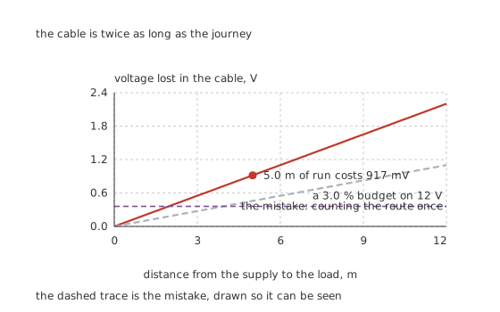
The dashed trace is the mistake, drawn so it can be seen.
Worked example — One run, worked properly
Take 8.0 A along a 5.0-metre run on a 12 V rail, in 1.5 square millimetres of copper at 17.2 nΩ·m.
The conductor is ten metres, not five, because the current goes out and comes back. That gives 115 mΩ of loop resistance.
At 8.0 A the drop is 917 mV — 7.64 % of the rail — and the cable turns 7.34 W into heat, permanently.
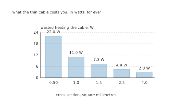
What the thin cable costs you, in watts, for ever.
Worked example — Sizing it from a budget instead of a guess
Set a budget: at most 3.0 % of the rail lost in the cable. That allows 45 mΩ of loop resistance at 8.0 A.
Solving the resistance relation for area gives 3.82 square millimetres, so the next stocked size up is 4.0, which lands at 2.87 % and wastes 2.75 W.
Fitting 0.50 instead — a size that looks perfectly substantial in the hand — gives 2.75 V of drop, 22.9 % of the rail, and 22.0 W heating the cable. That is not a subtle effect.
A voltage-drop budget is the thing to design against, because on a low-voltage run it is almost always the binding constraint. Three per cent is a common target and there is nothing sacred about it; what matters is knowing what the load will receive.
The resistivity in that calculation belongs to the metal, and copper is not the only choice. Aluminium has roughly sixty per cent more resistivity for the same cross-section, so an aluminium conductor has to be about a size and a half larger to match a copper one — and it is lighter and cheaper for it, which is why overhead distribution lines are aluminium and why it periodically reappears in building wiring. It also creeps under a clamped joint, oxidises into an insulator rather than a conductor, and expands more with temperature, so every one of its terminations is a specified part rather than a screw terminal. The electrical arithmetic is the same expression with a different number in it; the mechanical consequences are not.
Plated copper is copper for this purpose. Tinned or silvered strands change the surface, not the bulk, so the resistance calculation is unaffected at direct current. What the plating buys is solderability after years in a damp environment and, in the silvered case, a slightly better surface at the frequencies where only the surface is carrying anything.
Engineer
The gauge ladder, and what stranding changes
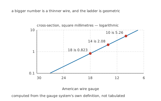
Computed from the gauge system's own definition, not tabulated.
Two systems name wire, and neither is intuitive. In much of the world a conductor is named by its cross-section directly, in square millimetres, which needs no explanation. The American wire gauge names it by a number that gets larger as the wire gets thinner, which needs a little.
Worked example — Why the gauge numbers behave the way they do
The gauge system is geometric by construction: each step is a fixed ratio in diameter, so a gauge number and a size are two ways of saying the same thing.
Working it out from that definition, gauge 14 is 2.08 square millimetres, gauge 18 is 0.823 and gauge 10 is 5.26.
Three gauge numbers is a factor of 2.01 in area, which is the rule of thumb worth carrying: three sizes thicker is twice the copper and half the resistance, and six is four times.
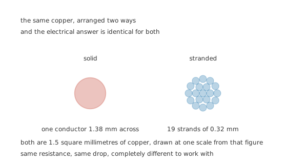
The same copper, arranged two ways, and the electrical answer is identical for both.
Stranding changes nothing electrical and everything else. The same cross-section is the same resistance whether it is one wire or nineteen. What differs is that a stranded conductor flexes repeatedly without the metal work-hardening and eventually cracking, that it terminates differently — a ferrule or a proper crimp rather than a screw terminal biting into loose strands — and that its overall diameter is slightly larger because of the gaps between the strands.
Solid conductor belongs where nothing moves. Fixed building wiring, breadboards, anywhere a wire is pushed into a spring terminal. Stranded belongs everywhere that flexes, and finely stranded belongs where it flexes constantly.
At high frequency the copper stops being fully used. Current crowds into the outside of a conductor, to a depth that falls with the square root of frequency. Working that out from its definition gives 9.33 millimetres at 50 Hz, which is deeper than most conductors are thick, so at mains frequency the effect can be ignored for ordinary sizes. At 1.0 MHz it is 0.0660 millimetres, and the middle of the wire is doing nothing at all — which is skin effect, and it is why high-frequency conductors are often flat, tubular or woven.
Professional
What the calculation misses
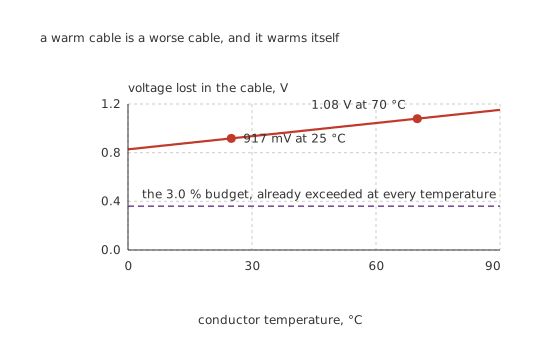
A warm cable is a worse cable, and it warms itself.
Worked example — It gets worse while it works
Copper's resistance rises with temperature at an illustrative 3.93 m per degree.
The run that dropped 917 mV at 25 °C drops 1.08 V at 70 °C — a factor of 1.18, taking it from 7.64 % of the rail to 9.00 %.
The cable heats itself with the 7.34 W it is wasting, so this is not a hypothetical: a cable working hard is a cable working worse.
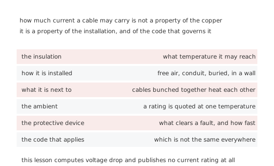
It is a property of the installation, and of the code that governs it.
Everything in that figure is why this lesson stops where it does. A cable's current-carrying capacity is a licensed question with a jurisdiction attached. The arithmetic above is not, which is exactly why the arithmetic above is the part worth learning: it travels.
The rest of what a cable is
The insulation is most of the specification. Its temperature rating sets what the conductor may reach; its voltage rating sets what it may separate; its material decides whether it survives oil, sunlight, abrasion or being walked on. PVC is cheap and unhappy in heat and ultraviolet; silicone is flexible and tolerates heat and tears easily; PTFE tolerates almost everything and costs accordingly.
Screened cable is a system decision. A screen only helps if it is terminated properly, usually at one end for low-frequency interference and at both for radio-frequency, and a screen connected at neither end is a decorative expense. Ground loops are what the one-end rule exists to avoid.
Twisting is cheaper than screening and often better. A twisted pair makes the loop area between out and back nearly zero, so it neither radiates nor picks up magnetically — and it is the reason a common-mode choke has anything to work with.
Terminate it the way the terminal expects. A ferrule on stranded wire into a screw terminal, a proper crimp with the proper tool, and no solder on a wire that will be clamped — the solder creeps under pressure and the joint goes loose months later.
Colour is a convention with legal force in places. Fixed wiring colours are set by code, not preference, and using them wrongly on a mains circuit is a hazard aimed at whoever opens the enclosure next.
Measure the drop rather than calculating it, when you can. Two probes, one at the supply and one at the load, under real load. The difference is the answer, and it includes every connector and joint the calculation forgot about.
Common mistakes
- Using the distance to the load instead of twice it — the conductor goes out and comes back, so a 5.0 metre run is ten metres of copper and twice the drop you calculated.
- Sizing by feel — 0.50 square millimetres looks substantial and loses 2.75 V of a 12 V rail at 8.0 A, which is 22.9 % and 22.0 W of heat.
- Assuming a code-compliant cable is electrically adequate — the 1.5 square millimetre run here loses 7.64 % of the rail, which many loads will not tolerate.
- Ignoring temperature — the same run drops 917 mV cold and 1.08 V at 70 °C, a factor of 1.18, and the cable is heating itself with the 7.34 W it wastes.
- Reading a gauge number as a size — a larger number is a thinner wire, and three gauge numbers is a factor of 2.01 in area.
- Soldering a wire that will be clamped — solder creeps under sustained pressure and the joint loosens after the product has shipped.
Frequently asked questions
How do I work out what size wire I need?
From a voltage-drop budget. Allow, say, 3.0 % of a 12 V rail at 8.0 A, which is 45 mΩ of loop resistance. Solving resistivity times length over area for the area gives 3.82 square millimetres, so fit the next stocked size up — 4.0, which lands at 2.87 % and wastes 2.75 W.
Why do I double the length?
Because the current has to return. A 5.0 metre run is ten metres of conductor, and using five metres halves every answer you get. It is the single most common error in this calculation.
How much current can this wire carry?
This lesson will not tell you, and it is not being coy. The answer depends on the insulation, on how the cable is installed and grouped, on the ambient temperature, on the protective device upstream, and on the wiring code that governs the installation — none of which is a property of the copper. Get it from the code that applies to you.
Is stranded wire electrically different from solid?
No. The same cross-section is the same resistance and the same voltage drop. The differences are mechanical: stranded flexes without work-hardening, terminates differently, and has a slightly larger overall diameter because of the gaps between strands.
Why does a bigger gauge number mean a thinner wire?
Because the number counts drawing operations, and each one makes the wire thinner. The system is geometric, so it behaves predictably: three gauge numbers is a factor of 2.01 in area, taking gauge 14's 2.08 square millimetres up to gauge 11's, or down to gauge 18's 0.823 at four steps further.