
Quick Answer
A current-sense resistor, or shunt, is a low-value resistor placed in a current path so the voltage across it reports the current through it. Sizing one trades signal against heat: a larger value gives a bigger voltage to measure and dissipates more power doing it.
Intuition
The weighbridge in the road
A weighbridge is a steel plate set into the road surface. A loaded truck drives across it without slowing down, and the plate reports what the truck weighs. It has to be two contradictory things at once — strong enough to carry the load, sensitive enough to measure it.
A current-sense resistor sits in a circuit the same way. It goes in series with the load, in the path the current was going to take anyway, and it has to be small enough that the circuit barely notices it and large enough that the voltage across it can be read by something. Every decision in this lesson comes out of that one tension.
The physics is Ohm's law used in reverse. Instead of picking a resistance to set a current, you accept whatever current the load draws and let a known resistance turn it into a voltage. A 25.0 mΩ shunt carrying 8.00 A produces 200 mV across itself. Amplify that, digitise it, and the software finally knows what the machine is drawing, which is how a charger decides it has finished and a supply folds back before anything melts.
The name shunt is older than the practice. It comes from the moving-coil era, when a low resistance in parallel with a meter movement carried most of the current and let the delicate part see a safe fraction of it. The resistor kept the name long after the movement went away.
Practitioner
Sizing one: signal against heat
Choose a shunt value and two numbers follow immediately, and they pull in opposite directions.
The sense voltage is proportional to the resistance, so a larger shunt gives a larger signal. The heat is proportional to the resistance too, and to the square of the current, which is the term that decides how physically big the part has to be:
Worked example — Sizing a shunt for a steady load
A load draws 8.00 A, and the shunt chosen for it is 25.0 mΩ.
The voltage across the shunt is 200 mV, and the heat inside it is 1.60 W.
That voltage is too small for most converters to use directly, so it goes through an amplifier of gain 20 volts per volt:
4.00 VAgainst a supply of 5.00 V that leaves headroom at the top and wastes very little of the range at the bottom.
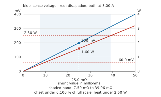
Two straight lines from the origin, on two different vertical scales, and one shaded band where both are tolerable.
Because both quantities grow together, the answer is a window rather than a value. The bottom of the window belongs to whatever reads the shunt. Every amplifier has an input offset voltage, an error that appears at its input whether or not a signal is present — here it is 60.0 µV. Decide that the offset may not eat more than 0.100 % of the full-scale sense voltage and the minimum falls out: the sense voltage has to reach 60.0 mV, which at 8.00 A takes at least 7.50 mΩ.
The top of the window is thermal. Take a part rated 5.00 W and run it at half of that, which is ordinary practice for anything that spends its working life warm (power ratings and derating). It may then dissipate 2.50 W, and at 8.00 A that caps the value at 39.06 mΩ.
Anything between 7.50 mΩ and 39.06 mΩ satisfies both ends, and 25.0 mΩ sits well inside with room on either side.
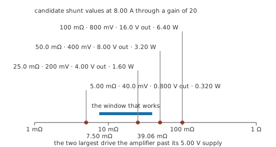
The two largest candidates ask the amplifier for more output than its supply can give.
A shunt also does two things the window says nothing about. It drops voltage the load no longer gets, which matters on a battery-fed circuit where every millivolt is range, and matters more the smaller the supply is. And a shunt in a return path lifts that return above ground by the sense voltage, so any circuit that thought it shared a ground now does not. The general form of that problem, an instrument becoming part of the thing it measures, is meter loading, arriving here from the other direction.
Engineer
Four terminals, and why two will not do
Here is the awkward fact about measuring a resistance of a few tens of milliohms: the solder joints at its ends are a meaningful fraction of it. A joint, its pad and the trace leading to it might come to 0.250 mΩ, and there is one at each end. If the sense wires are taken from the pads, everything between them is what gets measured:
That gives 25.5 mΩ instead of 25.0 mΩ, so every reported current is high by 2.00 % before any other error has been counted. Worse, the joints are the least repeatable part of the assembly: they vary with the solder profile, with rework, and with how the board ages.
A four-terminal, or Kelvin, part solves this by geometry rather than by calibration. The element is brought out on four connections: two heavy current terminals at the ends, and two sense terminals that touch the element at points inboard of them. The sense pair feeds a high-resistance amplifier input, so it carries essentially no current, drops essentially nothing, and reports the voltage between two points on the element itself. The joints stay in the current path, where they are harmless, and stay out of the measurement, where they were not.
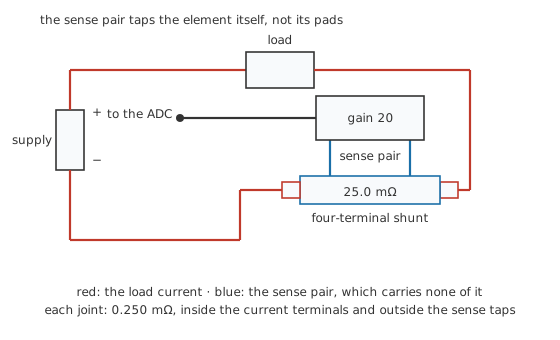
One closed loop for the load current, and a separate pair that only looks.
The same trick appears whenever a small resistance has to be measured honestly, which is why four-wire connections turn up on bench ohmmeters and precision sources as well as on shunts. Where a two-terminal part is unavoidable, the next best thing is a deliberate sense pattern on the board: two dedicated tracks that meet the pads at a single point each, carrying no load current of their own.
Adding up what is left
With the connection fixed, the remaining errors are the part's own and the amplifier's. Suppose the shunt is specified to 1.00 %, a tight but ordinary figure for a part built for this job (tolerance and precision). The amplifier's 60.0 µV of offset is 0.0300 % of a 200 mV signal, which at full current is nothing at all. Temperature adds the rest, and it gets its own section below.
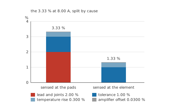
Every one of these is arithmetic on the values named above rather than a measurement.
Sensed at the pads the worst case totals 3.33 %. Sensed at the element it is 1.33 %. Nothing about the resistor changed between those two stacks, and the larger single contribution was never in the resistor at all.
Warm shunts read high
A shunt converts current to heat as an unavoidable side effect, and its own resistance moves with the temperature that heat creates.
Take a coefficient of 75.0 ppm/°C, which is realistic for the alloys these parts are made from, and a rise of 40.0 °C above the temperature at which the system was calibrated. Some of that rise is the shunt heating itself and some is the enclosure being warm; the arithmetic does not care which. The value becomes 25.075 mΩ, up by 0.300 %.
The direction is the one that catches people out. A larger resistance produces a larger voltage for the same current, and the system divides that voltage by the value it was told, so a warm shunt reports a current that never flowed. At 8.00 A the phantom is 24.0 mA.
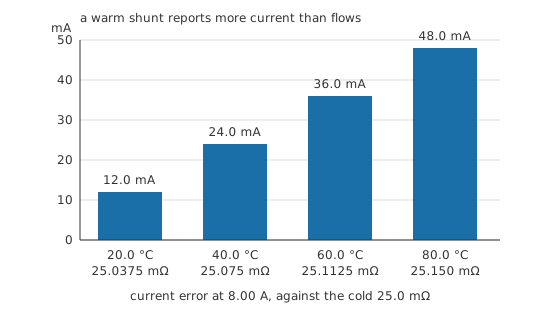
The bars carry the error in the reported current, because a 0.300 % shift in the value itself is not visible at any honest scale.
This is why sense resistors are sold with tempco on the front of the datasheet and why the good ones use special alloys rather than ordinary resistor materials. It is also why a design that needs better than about a per cent measures the shunt's temperature and corrects for it, or arranges for the shunt never to get hot in the first place.
Safety
Putting a shunt into a circuit means opening the path the current takes, and closing it again with a joint that now has to carry everything the load draws. A joint that carries current badly gets hot, and a shunt that fails open in a battery or motor return interrupts a large current in an uncontrolled way. Size the connection for the current, not for the resistor.
A low-side shunt lifts the load's return above the system ground by the sense voltage. That is fine on a bench and less fine when several boards assume they share a ground, and it is worth drawing before it is worth building. A high-side shunt avoids that, at the cost of an amplifier whose inputs sit at the supply rail rather than near ground.
Nothing in this lesson asks you to measure a current by making a path for it through an instrument. The figures here are arithmetic on the component values named in the text, and none of them describes an experiment worth running.
Professional
What reads the shunt, and what the shunt is made of
Layer 3 counted the errors at full current, where the amplifier's offset was too small to notice. Turn the current down and that stops being true, because the offset is fixed while the signal is not.
At 100 mA the shunt produces 2.50 mV, and the same 60.0 µV is now 2.40 % of it. Somewhere between those two currents the offset stops mattering and the tolerance takes over, and that point is worth knowing: it is 240 mA, the current at which the offset error equals the 1.00 % tolerance.
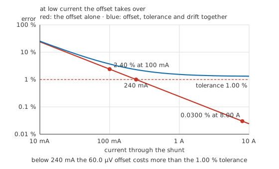
Below the crossing the amplifier owns the error; above it the resistor does.
A shunt therefore has a usable range rather than a single accuracy, and the range is set at the bottom by the amplifier and at the top by heat. Where a circuit has to measure both a sleeping load and a full one, the honest answers are a better amplifier, two shunts with a switch between them, or accepting that the low end is a rough number.
Checking the sense voltage on the bench brings the instrument's own error into it. A handheld meter specified at 0.500 % of reading plus 3 counts, on a range whose last digit is 0.100 mV, gives:
which is 1.30 mV on a 200 mV reading, or 0.650 %. That is larger than the shunt's own tolerance, so a meter of this class can confirm that the shunt is roughly right and cannot calibrate it. Accuracy, resolution and measurement error sets out how those two specifications combine.
Why a shunt looks the way it does
A sense resistor is usually a flat strip of alloy with heavy end terminations, and the shape is not styling. Resistance comes from resistivity and geometry:
Take an illustrative resistivity of 0.500 µΩ·m, a round figure rather than a catalogue one. A strip 50.0 mm long, 2.00 mm wide and 0.500 mm thick gives 25.0 mΩ. Reaching a low value with a real alloy needs generous cross-section and modest length, which is exactly the shape that also spreads 1.60 W over enough surface to lose it. A compact part of the same value would run hotter, drift more, and need the derating in Layer 2 applied harder.
The alloy matters as much as the shape. Ordinary resistor films have temperature coefficients in the hundreds of parts per million per degree; the alloys used for sense resistors are chosen because theirs are much smaller over the working range. Some of them are also chosen for a low thermoelectric voltage against copper, which stops the junction between the shunt and the board behaving as a small thermocouple in series with a signal already measured in millivolts.
Two more properties surface in fast circuits. A shunt has inductance, small but not zero, and in a switching converter the current changes fast enough that the inductive part of the voltage can rival the resistive part; parts sold for that job publish the figure and are built to keep it low. And a shunt in a high-frequency path shows the same skin and proximity effects any conductor does, so its resistance at a switching edge is not quite its resistance at DC.
Other ways of measuring current exist and each gives something up. A Hall-effect sensor and a current transformer both read the magnetic field instead of the voltage, so neither one is in the current path and neither dissipates the load's power; the Hall device brings its own offset and drift, and the transformer works only on changing current. The shunt stays the default for the same reason resistors generally do: it is cheap, it is linear, and its error budget is a short list of numbers you can write down before you build anything. Where those numbers stop being good enough, choosing the right resistor is the wider version of the same argument.
Common mistakes
- Sensing a two-terminal shunt at its own pads — the solder joints land inside the measurement and add a few per cent that no calibration can hold, because the joints change with rework and with age.
- Sizing by sense voltage alone — the value that gives a comfortable signal may be dissipating several watts, and the part that survives that is bigger, more expensive and slower to cool than the one you drew.
- Quoting one accuracy for the whole range — the error at a tenth of full current is dominated by the amplifier, not the resistor, and a single percentage on a datasheet page hides that completely.
- Ignoring the direction of the temperature error — a warm shunt reads high, not low, so a system that is already working hard reports itself working harder still.
- Forgetting that the return is no longer ground — a low-side shunt puts the sense voltage between the load's return and everything else, which is invisible on a schematic that draws both as the same triangle.
Frequently asked questions
What is a current-sense resistor?
A low-value resistor placed in series with a load so that the voltage across it is proportional to the current through it. An amplifier and a converter turn that voltage into a number the rest of the system can use.
How do I choose the value?
Work out the two limits. The smallest value is whatever gives a sense voltage large enough that your amplifier's offset and noise are an acceptable fraction of it. The largest is whatever keeps the dissipation inside the part's derated rating at full current. Then take something comfortably inside that window.
Why do current-sense resistors have four terminals?
So the voltage is sensed at the element rather than at the solder joints. The joints carry the load current and have a resistance of their own; a two-terminal connection measures them along with the part, and a Kelvin connection leaves them out of the answer entirely.
Should the shunt go in the high side or the low side?
Low-side sensing is simpler, because the amplifier works near ground, but it puts the sense voltage between the load's return and system ground. High-side sensing keeps the return clean and needs an amplifier that tolerates its inputs sitting at the supply rail. Where a fault to ground has to be detected, high-side is the one that sees it.
Why does my current reading drift as the board warms up?
Because the shunt's resistance rises with temperature and the system divides by the value it was given, so a warm shunt reports more current than flows. Parts sold for sensing use alloys with small coefficients for this reason, and precision designs measure the shunt's temperature and correct for it.
Can I just use an ordinary low-value resistor?
For a rough reading, often yes. What you give up is the temperature coefficient, the four-terminal connection and the pulse handling, and you gain a part whose value is specified loosely because nobody expected it to be measured.