
Quick Answer
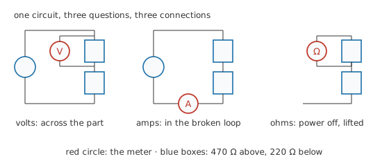
Voltage is measured across a part, with the circuit running and nothing disturbed. Current is measured through the circuit, which means opening the loop and putting the meter in the gap. Resistance is measured with the power off and at least one end of the part lifted clear.
Intuition
Each quantity asks for a different connection
The three basic measurements are not three settings of one operation. They are three different relationships between the instrument and the circuit, and the meter has to be wired differently for each.
Voltage is a difference between two points, so a voltmeter goes across the thing you are asking about, alongside it, with everything left connected and running. Nothing has to be undone, which is why it is nearly always the reading to take first.
Current is what passes through a path, so an ammeter has to become part of that path. The loop is opened and the meter bridges the gap, which means desoldering, unplugging or a link fitted for the purpose. That is real work, and it is the reason experienced people infer current from a voltage across a known resistance whenever they can.
Resistance belongs to a component rather than to a circuit, so an ohmmeter needs the component on its own. The power comes off first, because the meter works by pushing its own small current through the part and any other current present ruins that. Then one end is lifted, because everything else joining the same two points is in parallel with the part and the meter cannot tell them apart.
A doctor makes the same distinction. Taking a pulse needs contact and nothing more. Taking a blood sample means breaking the skin, and it is not done casually just because a number would be interesting.
Practitioner
Where the leads go, and what it costs
Take a supply set to 9.00 V feeding 470 Ω and 220 Ω in series, and work through all three quantities on it.
- Set the function and the jacks together. Volts and ohms share one red jack; current has its own. The most expensive mistake in this lesson is leaving the red lead in the current jack and then measuring a voltage.
- For voltage, put the probes on the two ends of the part with the circuit running. Black on the more negative end unless you want a minus sign, which is itself useful information.
- For current, switch off, open the loop, insert the meter, switch on. Choose the current range before making the connection, and start high if you are unsure.
- For resistance, switch off, wait for any capacitors to discharge, and lift one end of the part.
- Null the leads before any low-resistance reading. Touch the probes together, note what the meter shows, and either subtract it or use the meter's relative mode. Layer 3 shows how much this matters.
- Write down the reading with where it was taken. A voltage without a stated pair of points is not a measurement.
Two relationships cover the arithmetic. The chain divides the supply by proportion:
and any measured current through a known resistance gives back the drop across it, or the other way round:
Worked example — All three quantities on one chain
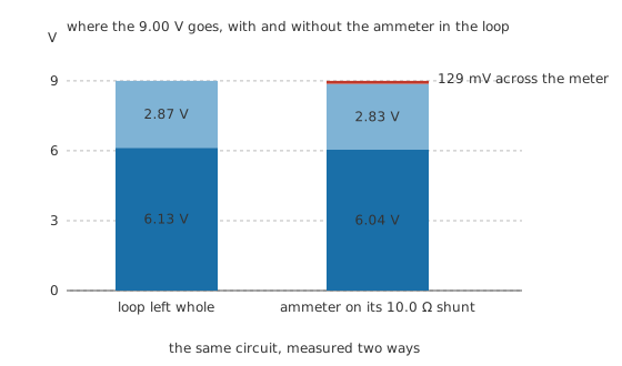
The two resistors total 690 Ω, so the supply drives 13.0 mA around the loop. That current puts 6.13 V across the larger resistor and 2.87 V across the smaller one.
Measure the voltage first, across each resistor in turn, and both figures appear with the circuit untouched. Their sum is the supply voltage, which is a free check on the pair of readings.
Now measure the current. Opening the loop and inserting the meter on a range whose shunt is 10.0 Ω raises the loop's total resistance to 700 Ω, so the current the meter reports is 12.9 mA, not the 13.0 mA that flowed before it arrived. The meter has taken 129 mV of the supply for itself. That is a reading -1.4 % away from the truth, caused entirely by the act of measuring.
That leaves the resistance. Powered down and with one end lifted, the meter reports it directly. Left in circuit, it would report the resistor in parallel with everything else joining those two points, which here is the rest of the chain and the supply.
Safety
Voltage readings here are taken with the circuit live, because that is the only way they exist. On bench supplies and batteries at these levels that is ordinary work. On mains-connected equipment it is a specialised job needing rated leads, a meter of the right CAT rating, one-handed technique and a plan for stored energy, and much of it can be done isolated instead.
Current measurement carries the hazard that gives this lesson its frontmatter flag. On a current range the meter is very nearly a wire. Put it across a source rather than into a break in the loop and you have made a bolted short through the instrument and through whatever your hands are touching. Never place a meter in series with a mains circuit to read current: a clamp meter reads current without opening anything and is the correct tool there.
Discharge before any resistance reading. A bulk capacitor that has been isolated for minutes can still hold a dangerous charge, and a failed bleed resistor leaves it charged indefinitely. Prove it at zero with the meter before touching the board. The full working practice is set out in electrical safety fundamentals.
Engineer
What each connection costs the circuit
Every measurement disturbs what it measures, and the three disturb it in different places.
The ammeter's share of the loop
An ammeter's shunt is in series with the circuit, so it steals voltage that the circuit's own components were using. The lower the current range, the larger the shunt, and the bigger the theft. On the same chain, three ranges give three answers: a 100 Ω shunt raises the loop to 790 Ω and reports 11.4 mA, -12.7 % out, having taken 1.14 V for itself. The 10.0 Ω shunt reports 12.9 mA, -1.4 % out. The 1.00 Ω shunt barely moves the loop at all, to 691 Ω, and reports 13.02 mA, -0.14 % out, on 13.0 mV of burden.
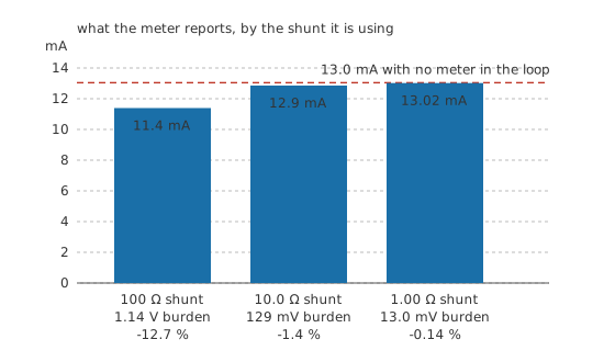
The voltage the shunt takes has a name, burden voltage, and it is the specification to look for on a meter you intend to use for current. It is also the reason the highest current range is often the most honest one even for a small current: the shunt is smallest there, and the resolution you give up may cost less than the burden you avoid.
The ohmmeter and the leads it looks through
An ohmmeter measures everything between its probe tips, and the leads are between its probe tips. With 0.20 Ω of lead and contact resistance, a true 0.100 Ω reads 0.300 Ω, which is 200 % high. A true 1.00 Ω reads 1.20 Ω, 20.0 % high. A true 10.0 Ω reads 10.20 Ω, only 2.00 % high.
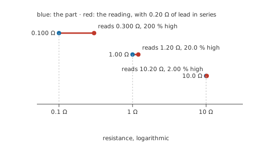
The offset is the same in every case. What changes is what it is being compared against, which is why nulling the leads is a formality on a kilohm and the whole measurement on a shunt. Below about an ohm even nulling stops being enough, because the contact resistance at the probe tips varies with how hard you press; a four-wire connection is the answer, and meter loading effects covers it.
Getting resistance without an ohmmeter
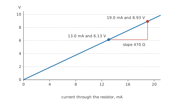
Two voltage readings at two known currents give a resistance without disturbing anything and without the leads mattering at all. The larger resistor drops 6.13 V at 13.0 mA; raise the supply until the current is 19.0 mA and it drops 8.93 V. Divide the change in voltage by the change in current and the answer is 470 Ω.
The question is the pair of points
A meter reports the difference between the potentials at its two leads and nothing else. Move one lead and you have asked a different question, and every answer is correct for the question actually asked.
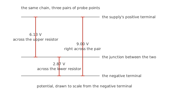
The productive habit is to park the black lead on the circuit's reference point and walk the red one around. Every reading is then a node potential, comparable against the schematic and against every other reading, and you have one hand free. Reserve the across-a-part measurement for the moment you have found the node that disagrees.
Professional
Measurements that need a different instrument
The three connections above cover steady quantities in an accessible circuit. Several common jobs fall outside that, and the honest answer is a different tool rather than more care with this one.
Current without opening the loop is the first. A clamp meter reads the magnetic field around a conductor and needs no electrical connection at all, which makes it the only sane way to read a mains current and the usual way to read a large one. Its resolution at low currents is poor by comparison, and the simple type reads AC only.
Very small resistances are the second. Below about an ohm, lead and contact resistance dominate whatever you do, and the four-wire method separates the current path from the sensing path so the sense leads carry almost no current and therefore drop almost nothing. Bench meters offer it on dedicated terminals.
Anything that changes quickly is the third. A handheld meter averages over a good fraction of a second, so a rail that collapses for a microsecond every time a motor starts reads perfectly healthy. The oscilloscope exists for exactly that gap, and a meter reading and a scope trace of the same node can disagree completely while both being right.
There is also the class of measurement where the circuit is fine and the instrument is the problem. On a high-impedance node the voltmeter's own input resistance draws enough current to move the reading; on a low-impedance one the ammeter's burden does the same in the opposite direction. Both are the same effect seen from two sides, and both are quantified in meter loading effects.
A reading is also a range rather than a point. The meter's specification says how far from the truth its number may be, and combining two such numbers into a third — dividing a voltage by a current to get a resistance, as this lesson does — combines their uncertainties too. Accuracy, resolution and measurement error works out what that leaves you with, and it is usually less precision than the display implies.
Common mistakes
- Putting an ammeter across a component instead of into the loop. It is a short circuit with a display on it, and the meter, its fuse or the circuit will settle the matter within a second.
- Measuring resistance with the circuit powered. The ohmmeter drives its own current through the part, and any other current present makes the answer meaningless or the meter dead.
- Reading a resistor in circuit and condemning it. Every other path between those two nodes is in parallel with it, so the number describes the board rather than the part.
- Skipping the lead null on a low-ohms reading. A fifth of an ohm of lead is nothing against a kilohm and is the entire reading on a shunt.
- Treating the current reading as the circuit's current. The meter's own shunt changed the loop the instant it was inserted, and on a low range it can change it a great deal.
- Taking a voltage without deciding first whether you want a node potential or a drop across a part. Both readings are honest, and only one of them answers your question.
Frequently asked questions
Why is a voltmeter connected in parallel and an ammeter in series?
Because voltage is a difference between two points and current is a flow through a path. A voltmeter has to touch both points, which puts it alongside the part. An ammeter has to carry the flow, which puts it in the path, so the path has to be opened first.
Can I measure current without breaking the circuit?
With a clamp meter, yes, by reading the magnetic field around the conductor. Otherwise you can read the voltage across a resistance already in the path and divide, which needs no unsoldering and disturbs nothing.
Why does my ammeter reading seem low?
The meter's shunt is in series with the circuit and takes a share of the supply, so the current genuinely falls when the meter joins the loop. On a 10.0 Ω shunt in a 690 Ω loop, the reading comes back 1.4 % low, and a higher range with a smaller shunt would be closer.
Why can I not measure a resistor while it is soldered in?
Everything else joining the same two nodes is in parallel with the part, and the meter measures the combination. It cannot separate the resistor from a second resistor, a winding or a return path through a neighbouring stage. Lift one end and the ambiguity goes away.
How do I measure a resistance below one ohm?
Null the leads first, and beyond that use a four-wire connection, which drives current through one pair of leads and senses the voltage with another pair that carries almost none. Failing that, pass a known current through the part and measure the voltage across it directly.