
Quick Answer
Parallel circuits connect components across the same two nodes, so every branch carries the full supply voltage while the branch currents add up to the total. The equivalent resistance of a parallel group is always smaller than its smallest branch, because each added branch is another path for current.
Intuition
One voltage, several paths
Components are in parallel when both ends of each one land on the same pair of points. A supply connected across those two points is connected across every component at once, so each of them gets the whole supply voltage rather than a share of it. That makes parallel the opposite arrangement to series, where the components form a single chain and it is the current that is common to all of them.
What differs between the branches is how much current each one lets through, and Ohm's law settles that branch by branch. Put 6 V across a 30 Ω resistor and a 60 Ω resistor wired this way. The first carries 0.2 A and the second 0.1 A; neither is affected by the presence of the other. The supply has to provide both at once, so it delivers 0.3 A.
Read the same figures from the supply's side and the less obvious half of the arrangement shows up. A supply pushing 0.3 A out at 6 V is facing a load of 20 Ω — below the smaller of the two resistors, never mind their sum. Adding a component to a circuit usually makes it harder for current to flow. Add one in parallel and you have opened a second route, so more current flows in total and the load looks easier.
House wiring is this arrangement, met before it is named. Sockets and light fittings sit in parallel across the incoming supply: each one gets the same voltage, each draws the current its own appliance needs, and switching one off leaves the others working.
Practitioner
Adding up the branch currents
A parallel calculation rests on the shared voltage and on what happens where the branches meet. Every branch has the same voltage across it, and the branch currents sum to the current the supply must deliver, which is Kirchhoff's current law applied to the node they share.
So the procedure is mechanical: take the common voltage, get each branch current from that branch's own resistance, add them. If what you want is the single resistance the supply appears to see, divide the common voltage by that total. Pairs of branches turn up more often than any other case, and they have a shortcut of their own:
Worked example — A second branch on an existing supply
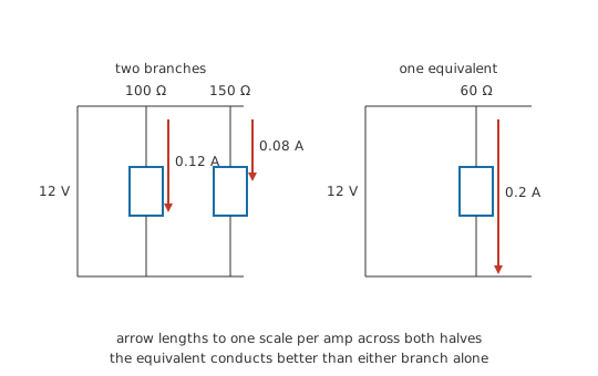
A regulated 12 V rail already feeds one resistive load of 100 Ω, which draws 0.12 A. A second load of 150 Ω is now wired across the same two rail points.
The first load does not notice. Its voltage has not moved, so its current has not moved either. The new branch takes V ⁄ R for itself, which comes to 0.08 A, and the rail now supplies I_total = I_1 + I_2 = 0.2 A.
Seen from the rail the pair is one resistance, and product over sum gives it as 60 Ω. Dividing the rail voltage by the total current brings back the same number, so each route checks the other at no cost.
Neither figure says whether the rail can cope. 60 Ω is a statement about the load alone, and a supply whose current limit sits below 0.2 A will sag, fold back or trip when the second branch is connected.

Past two branches, the rule to carry is the reciprocal one: the reciprocals of the branch resistances add, and the reciprocal of that sum is the equivalent resistance. Product over sum is that same rule solved for the two-branch case, and it holds only there. Handed three resistances at once it returns a number that means nothing, which Layer 3 works through. Work in pairs instead — combine any two branches, combine the result with the third, and carry on until one number is left. Equal branches shortcut further still: N resistors of the same value in parallel come to that value divided by N, so four identical resistors present a quarter of one of them.
The shared voltage has consequences at the bench too. An ohmmeter placed across one resistor of a parallel group reads the group, not the resistor, so in-circuit resistance measurements need a leg lifted before they mean anything. It also offers a way past the voltage altogether: when what you want is the split between branches, the current divider gets there in one step from the resistances. Most real networks are neither purely series nor purely parallel; the working method for those is in series-parallel networks.
Engineer
Conductances add
Call the shared voltage V. Branch k has V across it, so it carries I_k = V ⁄ R_k. Kirchhoff's current law at the node says the branch currents account for everything arriving from the supply, so I_total = I_1 + I_2 + … = V × (1 ⁄ R_1 + 1 ⁄ R_2 + …). Divide through by V. On the left is I_total ⁄ V, the equivalent conductance the supply sees; on the right is the sum of the branch conductances.
That is the general law for parallel branches, and in conductance it is an ordinary sum: G_p = G_1 + G_2 + … for as many branches as there are. The two-branch case needs no separate treatment, and there is no reciprocal of a reciprocal to keep track of. Conductance is sometimes presented as a curiosity — resistance turned upside down and given the unit siemens — and a parallel network is where that inversion is the natural way round. Series combination is addition in resistance; parallel combination is addition in conductance. Each arrangement has a quantity in which it is simple, and picking the right one removes most of the algebra.
Product over sum drops out of the general law in two lines. For two branches, G_p = 1 ⁄ R_1 + 1 ⁄ R_2, and over a common denominator that is (R_2 + R_1) ⁄ (R_1 R_2). Invert both sides and the familiar form appears. What matters in that derivation is where the two came from: the common denominator was built from two terms. A third term changes the numerator, and the shape of the answer with it.
Worked example — Three branches, two routes, one blunder
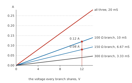
Add a third branch of 300 Ω to the pair from Layer 2. Taken in conductance the working is a straight addition — the branches contribute 10 mS, 6.67 mS and 3.33 mS, summing to 20 mS, whose reciprocal is 50 Ω.
The pairwise route arrives at the same place. Layer 2 already combined the first two branches into 60 Ω; put that through product over sum against the third branch and the answer is 50 Ω.
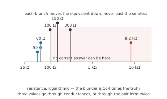
The blunder is to stretch the two-branch formula by eye until it covers all three. Multiply the resistances together, divide by their sum, and out comes 8.2 kΩ — larger than every branch in the circuit, where the true value has to be below the smallest of them. Product over sum is one algebraic case rather than a rule about products and sums, and a third term destroys it.
The bound is easiest to see in conductance too. Branch conductances are positive quantities, so their sum exceeds the largest single term, and the reciprocal of that sum is therefore below the smallest single resistance. Adding a branch can only add conductance. A parallel answer that lands above the smallest branch is a sum to redo, and spotting it takes a glance.
Both ends of the range behave sensibly. A branch that goes open-circuit has zero conductance and drops out of the sum, leaving the others untouched. A branch of zero resistance has unbounded conductance and takes the group to zero with it, which is the arithmetic statement of a short circuit — one shorted branch defeats every other branch in the group, however carefully they were chosen.
The derivation leans on one thing that gives way early in practice. "The same voltage across every branch" is exact only while the conductors joining the branches have no resistance of their own. Real copper does, so at high currents the drop along the interconnect puts each branch at a slightly different voltage, and each branch's own lead resistance adds in series with it. For signal-level currents the error is beneath the resistor tolerance. For a hundred amperes spread across paralleled devices, the copper layout decides the split more firmly than the devices do.
Professional
Sharing current between real devices
Resistors in parallel divide the current in the ratio their conductances set, and they keep dividing it that way however warm they get. A metal-film resistor's value shifts by parts per million per degree, far too little to move the split, so a group of resistors of equal value and ordinary tolerance shares to within roughly the tolerance itself, which is dependable enough to design around.
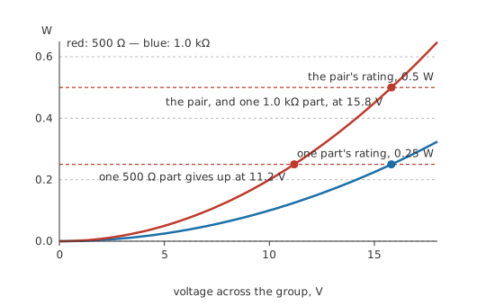
Dissipation is the commonest reason for doing it deliberately. A pair of 1.0 kΩ resistors rated 0.25 W each presents 500 Ω and will absorb 0.5 W, since equal branches take equal current and each handles half the total. Three of them give a third of the resistance at three times the power rating. Spreading the heat over several packages often helps more than the rating arithmetic suggests, since each package has its own path to the board and its own share of air.
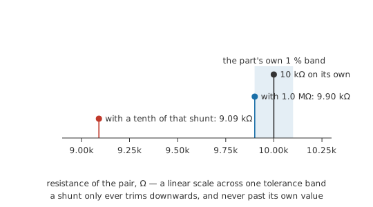
Awkward values are the other routine use. The E-series leaves gaps, and stock leaves larger ones. A high-value resistor across a stock value trims it downwards by a controlled amount: 1.0 MΩ across 10 kΩ yields 9.90 kΩ, about one per cent low, with the trim itself set by a ratio and so fairly insensitive to the shunt's own tolerance.
Semiconductor junctions do not behave like this at all, and the difference is thermal. A silicon diode's forward voltage falls as its junction warms, by roughly 2 mV per degree Celsius at a fixed current. Wire two diodes in parallel and they are forced to one common forward voltage, so whichever device happens to be warmer — a better solder joint to the copper, a hotter neighbour, an ordinary spread within the reel — conducts more of the load at that voltage. That extra current dissipates extra power in it, which warms it further and pulls its forward voltage down again. The loop feeds itself, and the usual end state is one device carrying nearly all the current until it fails. Paralleled bipolar transistors do the same thing through their base-emitter junctions.
The fix is to break the common-voltage assumption deliberately. A small ballast resistor in series with each device — an emitter resistor on a BJT, a series resistor per diode — means a device taking more current develops more drop of its own and is pushed back towards its share. Ballast wastes power by design, and choosing its value is a trade between sharing accuracy and efficiency.
Safety
Power diodes or bipolar transistors paralleled without ballast form a thermal-runaway path. The device that loses ends up carrying the full load current on its own, and in a mains-derived or battery-backed supply that failure can be energetic. Ballast each device, or specify one part rated for the entire current.
MOSFETs parallel readily, for the opposite thermal reason. A MOSFET held in full conduction behaves as a resistance, and that on-resistance climbs with junction temperature. A device drawing more than its share warms, its on-resistance rises, and current migrates to its cooler neighbours; the split corrects itself. Steady-state DC sharing between paralleled MOSFETs is stable enough that paralleling is the normal way to build a high-current switch. Gate drive and source inductance still have to be matched, because sharing during a switching transition is a dynamic problem no temperature coefficient addresses.
Redundancy is the other reason to build parallel paths on purpose: several bond wires to one die, multiple vias under a supply pad, several contacts on a connector pin, banks of capacitors where one would nominally do. Losing one path leaves the rest functioning, which is both the useful property and the diagnostic difficulty. Open one branch of the Layer 2 example and the survivor still sees its full 12 V and carries its usual 0.12 A; probing that branch reveals nothing. The reading that moved is the total, 0.2 A before the fault and 0.12 A after. With a dozen decoupling capacitors or eight vias feeding a rail the step is far smaller, and the fault surfaces as margin that used to be there. Supply current is where it shows up, since every branch that remains is behaving exactly as it should.
Before paralleling anything that is not a resistor, work out which way its voltage drop moves as it heats. A drop that falls needs ballast, while one that rises lets the devices share on their own.
Common mistakes
- Applying product over sum to three branches at once — the formula is the reciprocal rule solved for two branches, and it holds only there. Combine two branches, then combine that result with the third.
- An equivalent resistance that lands above one of the branches — that answer is wrong before anything else is checked. The parallel combination of positive resistances always comes out below the smallest of them.
- Measuring one resistor of a parallel group in circuit. The meter reads the whole group through the other branches. Lift a leg first, or take the reading before the board is populated.
- "They are the same part number, so they will share" — true of resistors, false of diodes and bipolar transistors, whose forward voltage falls as they warm. Matched part numbers do not produce matched junction temperatures.
- Expecting supply current to hold steady as branches are added — each branch is another route, so the total rises while every existing branch carries on exactly as before. The supply is what runs out first.
- Forgetting that the shared node is made of copper. Branch voltages are equal only to the extent the interconnect between them has no resistance, and at high current the trace between two paralleled devices is part of the circuit.
Frequently asked questions
What stays the same in a parallel circuit, and what divides?
Voltage is common to every branch; current divides between them. Each branch draws whatever its own resistance permits at that voltage, and the branch currents add to the total the supply must deliver.
Why is the equivalent resistance smaller than the smallest resistor?
Each branch is an additional path for current. Conductances add when branches are in parallel, so the group conducts better than any single branch does, and better conduction means lower resistance. Adding a branch can only push the result down.
Can product over sum be used for three or more resistors?
Only in pairs. Combine two branches into one equivalent, feed that into the same formula with the third, and repeat. Used on three resistances in a single step it returns a value larger than any branch, which cannot be correct.
What happens to a parallel circuit when one branch opens?
The remaining branches carry on unchanged, since they still have the same voltage across them. Total supply current falls by whatever the missing branch was taking, and the equivalent resistance of the group rises.
Why do paralleled diodes need ballast resistors when paralleled resistors do not?
A diode's forward voltage drops as it heats, so at a shared voltage the warmer device takes more current and heats further still. A series ballast turns that extra current into extra drop and pushes the device back towards its share. Resistors have no such positive feedback.
Is house wiring series or parallel?
Parallel. Every socket and light fitting sits across the same incoming pair of conductors, so each receives the full supply voltage and switching one off leaves the others alone.