
Quick Answer
A diode is a two-terminal part that conducts when current tries to flow from anode to cathode and blocks it in the other direction. Conducting costs a roughly fixed voltage drop, near 0.7 V for silicon. The printed band marks the cathode, and reverse voltage, average current and that drop are what you select on.
Intuition
The ratchet in a socket wrench
Turn a socket wrench one way and the nut turns with it. Turn it back and the handle swings freely while the nut stays put, clicking as it goes. The tool has a direction, and the direction is built into it rather than being something you have to remember to do.
Two details of that ratchet matter more than the obvious one. First, going the useful way is not completely free: you have to push hard enough to make the pawl ride over each tooth, and below that effort nothing happens at all. Second, the free direction is not perfectly free either, because the pawl still drags a little.
A diode does exactly this for electric current. Current entering the terminal called the anode and leaving by the one called the cathode meets very little opposition. Current trying to go the other way meets an enormous amount. And the same two details apply: conducting costs a small voltage, and blocking is very good rather than perfect.
The reason is the whole of the previous lesson. A diode is one PN junction with a wire on each side. Forward bias lowers the barrier the junction built for itself and carriers pour across; reverse bias raises it and almost nothing does. Everything below is the practical consequence.
The schematic symbol is a triangle pointing at a bar. The triangle points the way conventional current is allowed to go, and the bar is the cathode. On the real part, the cathode carries a printed band, so the symbol and the component agree with each other by convention rather than by accident.
Practitioner
Working with the drop
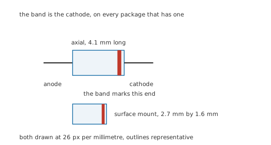
The band is the cathode, on every package that has one.
For everyday work a silicon diode is a switch that is closed one way, open the other, and drops 0.70 V while closed. That model gets most circuits right, and it is enough to size the resistor in front of it.
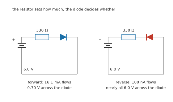
The resistor sets how much, the diode decides whether.
Worked example — The current in a simple diode loop
Put a 6.0 V supply, a 330 Ω resistor and a forward-biased diode in one loop. The diode takes 0.70 V, so the resistor gets what is left, and the current is 16.1 mA.
Ignore the drop and you would have predicted 18.2 mA, which is 13.2 % too high. Small circuits are exactly where that matters.
Turn the supply round and the current becomes the diode's leakage, near 100 nA for a small part at room temperature. That is a ratio of 161 k between the two directions, which is what "one way" actually means.
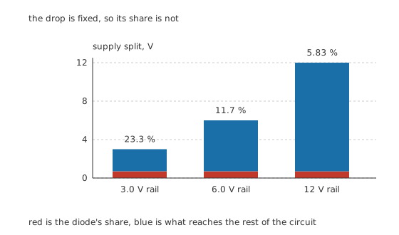
The drop is fixed, so its share is not.
The drop is roughly constant, so its importance depends entirely on the rail it sits on. On 12 V it takes 5.83 % of the supply and nobody notices. On the 6.0 V rail above it is 11.7 %, still a detail. On 3.0 V it takes 23.3 %, and a battery-powered design that throws away nearly a quarter of its voltage has a real problem. That single arithmetic is why Schottky diodes exist.
The drop also becomes heat. At 16.1 mA the diode dissipates 11.2 mW while the resistor dissipates 85.1 mW, so on a small-signal circuit the diode is not the part to worry about. Scale the current up by two orders of magnitude and it is the only part to worry about.
Engineer
Where the simple model stops being true
The constant 0.70 V is a convenience, not a property. A junction's forward voltage rises slowly with current and falls as the part warms up, and both effects are large enough to matter in real designs. Diode I-V characteristics measures the first and diode models puts numbers on when the constant is good enough.
Two consequences follow immediately. Two diodes of the same type never share current equally if you simply wire them in parallel, because the one that happens to conduct slightly better gets warmer, which makes it conduct better still. And a diode used as a voltage reference drifts with temperature, which is a defect in one circuit and the operating principle of a temperature sensor in another.
The two current ratings, and why there are two
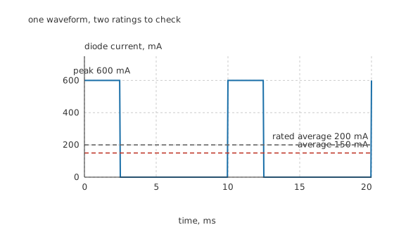
One waveform, two ratings to check.
A datasheet gives an average forward current and a separate surge or peak current, and they protect different things.
Worked example — A pulsed load against both ratings
A load draws 600 mA for 2.5 ms out of every 10 ms, a duty of 0.25, so the average is 150 mA.
Against an average rating of 200 mA that is comfortable. The peak is a separate question, and the 2.0 A surge rating is not the number that answers it — that rating covers a single event like inrush, not a peak that repeats every cycle. A repeating peak is checked against the datasheet's repetitive-peak rating, a separate and lower number.
The average rating is about heat: the junction has to lose the power it makes, and heat flows on a timescale of seconds. The peak rating is about the bond wire and the junction's own thermal mass on a timescale of microseconds, where nothing has time to spread out. A capacitor-input rectifier draws its current in tall narrow spikes and stresses both ratings very differently, which is the whole subject of smoothing capacitors and ripple.
Which limit binds
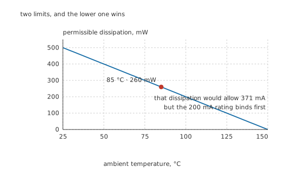
Two limits, and the lower one wins.
Dissipation ratings are quoted at one temperature and fall linearly to zero at the maximum junction temperature, exactly as resistor power ratings do.
Worked example — Derating, and the limit that actually applies
A part rated 500 mW at 25 °C with a maximum of 150 °C may only dissipate 260 mW once the surroundings reach 85 °C.
At 0.70 V per amp, that dissipation would allow 371 mA. The part's own average-current rating is 200 mA, so here it is the current rating that binds and not the heat. Check both, every time, and never assume which one wins.
Professional
Choosing one, and what goes wrong
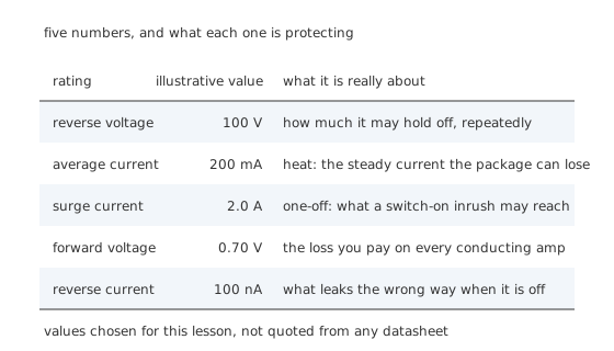
Five numbers, and what each one is protecting.
Selection is a short list, and the trap is that the numbers on it interact.
Reverse voltage first, with margin. The repetitive peak reverse rating, 100 V for the illustrative part in the figure, is what it may hold off cycle after cycle, and exceeding it does not fail gracefully. Rectifier circuits routinely present a diode with more reverse voltage than the supply they run from: a capacitor-smoothed half-wave rectifier puts nearly twice the peak across its diode, and an inductive load with no clamp puts hundreds of volts across it. Doubling the calculated figure is normal practice.
Then current, both kinds, at the real ambient. Working through the derating at the temperature inside the enclosure rather than at the bench is where most surprises live.
Then the drop, if the rail is low or the current is high. Below about five volts, or above about an amp, the drop stops being a detail and becomes the design.
Then leakage, if the circuit is high impedance. 100 nA through a megohm is a millivolt and irrelevant; the same leakage into the gate of a slow integrator is the whole error. Leakage also roughly doubles for every ten degrees, so a part that is fine on the bench can be useless in a hot enclosure.
Failure, and how it presents
A diode that has been driven past its reverse rating or its junction temperature usually fails short, not open. That matters because a shorted diode in a rectifier presents as a blown fuse or a dead transformer rather than as a diode fault, and because a shorted protection diode looks exactly like a working one until you take it out of circuit. Testing diodes covers separating those cases, and the continuity and diode test ranges on a meter are the tools for it.
The rarer failure is open, and it comes from mechanical damage or from a surge that vaporises the bond wire rather than melting the junction. An open diode in a rectifier halves the output and doubles the ripple rather than killing it, which is a much harder fault to find.
Two habits worth having
Never parallel diodes to get more current without a resistor in series with each. The current sharing is unstable, and the value only has to be large enough that its drop dominates the difference between the two forward voltages.
Never leave an inductive load without a path for its current. Switching off a relay or a motor winding puts the coil's stored energy into whatever is nearest, and a diode across the coil is the standard answer. Flyback diodes is the lesson for it, and the failure it prevents is the transistor that switches the coil, not the coil itself.
Common mistakes
- Fitting a diode backwards and expecting nothing to happen — a reversed diode in a supply blocks it entirely, and a reversed diode across an inductive load conducts continuously and destroys itself.
- Treating the forward drop as exactly 0.7 V at any current — it rises with current and falls with temperature, and both matter as soon as the current is large or the rail is small.
- Checking only the average current rating — a capacitor-input rectifier or any pulsed load can sit inside its average rating while exceeding the peak rating several times over.
- Sizing the reverse rating from the supply voltage — many common circuits put more than the supply across the diode, and some put many times more.
- Paralleling diodes for extra current — the one with the lowest drop takes most of the current, warms up, and takes more still, unless each has its own series resistor.
Frequently asked questions
Which end of a diode is the cathode?
The end with the printed band. In the schematic symbol it is the bar that the triangle points at, and conventional current flows in through the anode and out through the cathode. On a surface-mount part the band is usually a bar or a notch printed on the body at the cathode end.
How much voltage does a diode drop?
For a silicon diode at ordinary currents, roughly 0.7 V. The exact figure rises slowly with current, falls by about two millivolts for every degree the part warms, and depends on the type: a Schottky diode drops perhaps half as much, and a light-emitting diode drops considerably more.
What happens if I put too much reverse voltage across a diode?
It breaks down and conducts, and unless the current is limited it usually fails short. Ordinary rectifier and signal diodes are not designed to survive that, which is what separates them from Zener and TVS diodes, both of which are built to break down at a defined voltage without being damaged.
Why does a diode need two current ratings?
Because heat and mechanical stress happen on different timescales. The average rating protects the junction from a steady temperature rise, which takes seconds to develop. The surge rating protects the bond wire and the junction from a brief current that ends before anything has time to spread the heat out.
Can I use a bigger diode than the circuit needs?
Usually yes, and it is often the cheap answer for reverse voltage. The costs are size, cost, and two electrical ones: a physically larger junction leaks more and has more capacitance, so in a fast switching circuit or a high-impedance one, an oversized part can be a worse choice than a correctly sized one.