
Quick Answer
A diode's forward current rises exponentially with its forward voltage, so every extra 60 mV or so multiplies the current by ten. There is no threshold anywhere on the curve. The familiar 0.7 V is simply where that curve passes through the currents ordinary circuits use, and it moves with current and temperature.
Intuition
The mould that appeared overnight
A loaf sits in the bread bin for four days and looks fine. On the fifth morning it is covered. Nobody would claim the mould switched on overnight, because mould does not work like that: it doubles, quietly, from a start too small to see, and the day it "appears" is simply the day its steady doubling crossed the size your eye can pick out.
A diode's current does the same thing, and it produces the same illusion. Draw the current against the voltage on an ordinary scale and you get a line lying flat along the bottom until somewhere near half a volt, then rising almost vertically. It looks exactly like a threshold. It is not one.
What is actually happening is that the current multiplies for every fixed step in voltage, all the way down. At a fifth of a volt the diode is conducting; it is conducting a few billionths of an amp, which no ordinary meter shows and no circuit notices. Add a little more voltage and the current is a thousand times larger, and a little more again and it is a thousand times larger still.
So "the diode turns on at 0.7 V" is a statement about the currents we happen to care about rather than about the diode. Pick milliamps and the number is nearer half a volt. Pick an amp and it is nearer three quarters. The curve underneath never changes, and knowing that is the difference between using the 0.7 V rule correctly and being surprised by it.
Practitioner
Reading the curve
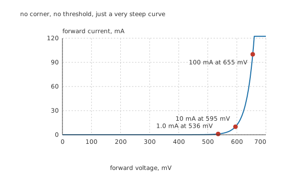
No corner, no threshold, just a very steep curve.
The shape above is not sketched. It comes from the standard model of a junction, evaluated at a saturation current of 1.0 pA and an ideality factor of 1.0.
The one number that makes the rest usable is the thermal voltage, which at 300 K is 25.85 mV. Multiply it by the natural logarithm of ten and you get 59.5 mV, which is what a decade of current costs.
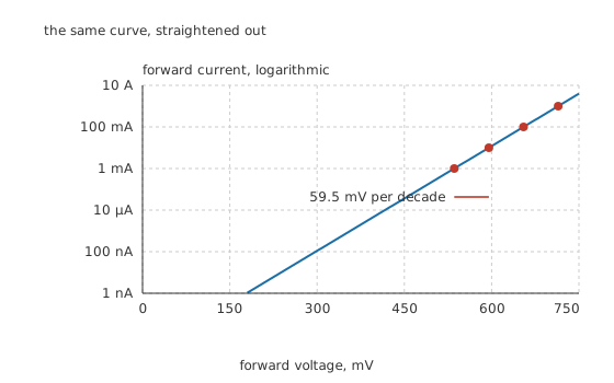
The same curve, straightened out.
Worked example — What the diode drops at four decades of current
Running 1.0 mA through this diode needs 536 mV.
Ten times that, 10 mA, needs 595 mV, which is one decade further along and therefore 59.5 mV more.
100 mA needs 655 mV, and 1.0 A needs 714 mV.
Across a thousandfold change in current the drop moved by 179 mV.
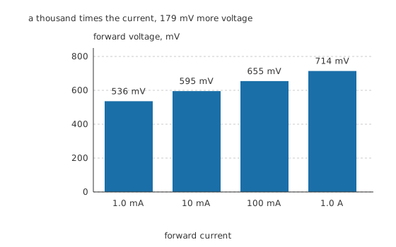
A thousand times the current, 179 mV more voltage.
That last figure is the practical point of the whole lesson, and it cuts both ways. A drop that moves by 179 mV across three decades is nearly constant, which is exactly why treating it as a fixed number works so well. But the fixed number you choose has to be the one that belongs to the current you are running, and quoting 0.7 V for a circuit passing a milliamp overstates the drop by around a sixth of a volt.
Engineer
Solving a circuit that contains one
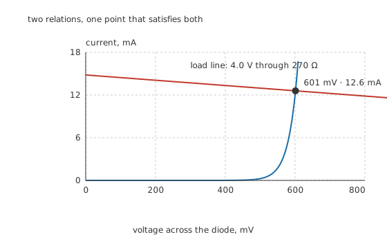
Two relations, one point that satisfies both.
A diode in a circuit obeys two things at once. It obeys its own curve, and it obeys whatever the rest of the circuit demands, which for a resistor from a supply is a straight line.
The straight line runs from the supply voltage at zero current to the short-circuit current at zero volts, and it is called the load line. The circuit settles where the two meet, because that is the only place both relations hold.
Worked example — Finding the operating point of a diode and a resistor
A 4.0 V supply drives 270 Ω in series with the diode above.
The two relations meet at 601 mV across the diode, passing 12.6 mA.
There is no closed-form answer here, because one relation is a straight line and the other is an exponential. This figure was solved numerically, by narrowing the interval until both agreed, which is exactly what a circuit simulator does and what diode models shows you how to avoid when a rough answer will do.
The slope at that point, and why it matters
Around the operating point, a small change in voltage produces a proportional small change in current, and the ratio between them behaves like a resistance. It is not the diode's DC resistance, which would be 601 mV divided by 12.6 mA and is a much larger and much less useful number.
Worked example — What a small signal actually sees
At 12.6 mA, the small-signal resistance is 2.05 Ω.
That is what a millivolt of ripple riding on the supply sees, and it falls in inverse proportion to current: run ten times the current and the slope resistance is a tenth. A conducting diode is therefore a fairly good, current-controlled, small-value resistor, which is the basis of several attenuator and mixer circuits and part of why Zener regulators hold their output as well as they do.
Professional
Where the model breaks, and what the reverse side does
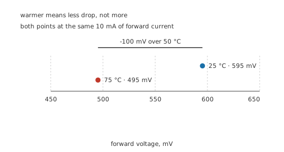
Warmer means less drop, not more.
The model above holds the saturation current fixed, and if you take it literally it predicts that a warmer diode drops more, because the thermal voltage rises in proportion to absolute temperature. Measurement says the opposite, and the discrepancy is worth understanding rather than papering over.
The resolution is that the saturation current is itself strongly temperature-dependent, and it climbs far faster than the thermal voltage does. That effect wins, and the net result is the empirical figure every datasheet quotes: about -2.0 mV/°C at a fixed current.
Worked example — The drop at a hot junction
Take the diode at 10 mA, where it drops 595 mV at 25 °C.
Warm it to 75 °C, a rise of 50 °C, and the drop falls by -100 mV to 495 mV.
That is a large change for a circuit that treated the drop as a constant, and it is the reason a diode makes a serviceable temperature sensor. It is also why paralleled diodes share current so badly: the warmer one drops less, so it takes more current, so it gets warmer.
The reverse side
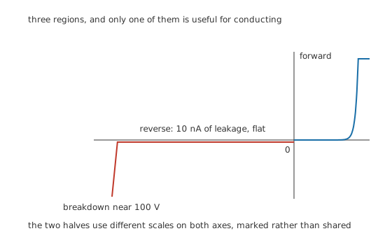
Three regions, and only one of them is useful for conducting.
Reverse-biased, the same model predicts a current that saturates at the saturation current and stops changing, and that is broadly what happens. A real small-signal diode leaks around 10 nA at room temperature, and the number barely depends on how much reverse voltage you apply.
It depends enormously on temperature. Leakage roughly doubles for every ten degrees, so the same part at 75 °C leaks about 320 nA. In a low-current circuit that is the difference between a working design and a drifting one, and it is why the PN junction lesson treats reverse current as a generation rate rather than as a conduction.
Push the reverse voltage far enough, near 100 V for this part, and the field inside the depletion region tears carriers loose and the current rises without limit. An ordinary diode is not built to survive that. A Zener diode is built to do exactly it, at a defined voltage, without damage.
Three things the exponential leaves out
Series resistance. At high currents the bulk material and the bond wires add a real resistance in series with the junction, so the curve bends away from the exponential and towards a straight line. Above an amp or so on a small part, most of the extra drop is resistive rather than junction voltage, and no adjustment to the ideality factor fixes that.
High-level injection. As the injected carrier density approaches the doping density, the exponent's effective ideality factor drifts from one towards two. The model still works, but with a parameter that is not really constant.
Junction capacitance. The curve says nothing about time. A junction that has been conducting has stored charge that has to be removed before it can block, and a reverse-biased junction is a capacitor that has to be charged. Neither appears anywhere on a static curve, and both dominate at speed. That is the subject Schottky diodes exists to address.
Common mistakes
- Believing a diode switches on at a threshold voltage — the curve is smooth and exponential everywhere, and the apparent corner is an artefact of a linear current axis.
- Using 0.7 V at every current — the drop for this part runs from 536 mV at 1.0 mA to 714 mV at 1.0 A, so the constant has to match the current the circuit actually runs at.
- Forgetting that the drop falls as the part warms — about two millivolts per degree, which over a fifty degree rise is a hundred millivolts and is why paralleled diodes never share current.
- Assuming reverse leakage is negligible because it is negligible on the bench — it roughly doubles every ten degrees, so a nanoamp at room temperature is a very different number inside a hot enclosure.
- Treating the diode's small-signal resistance as its DC resistance — a small signal sees the slope of the curve at the operating point, which is far smaller than voltage divided by current and falls as the current rises.
Frequently asked questions
What is the forward voltage of a diode?
There is no single figure. It is whatever the exponential curve requires at the current you are passing. For an ordinary silicon diode it lands near 0.6 V at a few milliamps and near 0.7 V at a hundred, and every decade of extra current adds roughly 60 mV to it.
Why is a diode's I-V curve exponential?
Because the current across the junction is set by how many carriers have enough energy to climb the potential barrier, and the fraction of carriers above any energy falls off exponentially. Bias changes the barrier height directly, so the current changes exponentially with bias.
How do I find the current in a circuit with a diode in it?
Draw or compute the load line for the rest of the circuit, which for a supply and a resistor is a straight line from the supply voltage to the short-circuit current, and find where it crosses the diode's curve. There is no algebraic solution, so it is either graphical, numerical, or an approximation using a simplified diode model.
Does a diode's forward voltage go up or down with temperature?
Down, by roughly two millivolts per degree at a fixed current. The thermal voltage in the exponent does rise with temperature, but the saturation current rises much faster, and the net effect is a falling forward voltage. It is a reliable enough relationship to use for temperature measurement.
What is the small-signal resistance of a diode?
It is the slope of the I-V curve at the operating point, and it works out as the ideality factor times the thermal voltage divided by the bias current. At 10 mA that is a couple of ohms. It falls in inverse proportion to current, which makes a forward-biased diode a usable voltage-controlled attenuator element.