
Quick Answer
A half-wave rectifier is one diode in series with the load. It passes the half of each cycle that drives current the right way and blocks the other half, so the output is a train of gaps and humps. Its average is the peak divided by pi, and the diode must hold off the full peak.
Safety
Every rectifier in this lesson is fed from a transformer secondary at a low voltage, and every number here belongs to that secondary. A rectifier connected directly to the mains has no isolation at all: its output has no safe reference to earth, and a probe clipped to it can put mains potential where you did not expect it. Do not extrapolate this lesson to a mains-connected circuit without the isolation and the training that work needs.
Intuition
The shop open mornings only
A corner shop that opens only in the mornings still feeds the street. You get everything you need from it, and the supply is entirely reliable in the sense that it is there whenever it says it will be. It just is not there for most of the day, so the household has to be built around the gap: buy enough while it is open, and have somewhere to put it.
That is a half-wave rectifier. Alternating current pushes one way and then the other. A diode passes only the pushes that go the right way, so half of every cycle reaches the load and half never arrives at all. The output is not steady. It is a series of humps with flat gaps between them, and every circuit that runs from one has to be built around those gaps.
The obvious question is why anyone would throw away half of a perfectly good supply, and the honest answer is cost. One diode is the cheapest way to get current flowing in one direction only, and where the load is small, tolerant, and cheap, that is the end of the design. Small mains adapters, trickle chargers and the supply rails inside inexpensive appliances have all been built this way for a century.
The less obvious question is what "average" means for a shape like this, and that turns out to matter more than the missing half. A meter set to read DC volts reports one number, a meter set to read AC reports another, and neither of them is the peak. All three are true and they describe different things.
Practitioner
What comes out
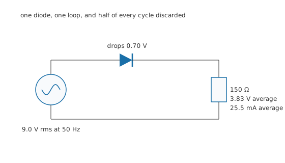
One diode, one loop, and half of every cycle discarded.
The circuit is one diode in series with the load, fed from a transformer secondary. Current can only go round the loop while the top of the secondary is positive with respect to the bottom, and only then by more than the diode's drop.
A transformer is specified in rms volts, so the first step in every rectifier calculation is getting to the peak.
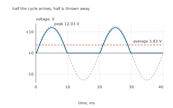
Half the cycle arrives, half is thrown away.
Worked example — What a 9.0 V secondary actually delivers
A 9.0 V rms secondary has a peak of 12.73 V, and reading the relation back the other way confirms it at 9.0 V.
The diode's 0.70 V comes off the top of every hump, so the output peaks at 12.03 V.
Averaged over the whole 20 ms period, with 1.0 conducting half-cycle in each one, that is 3.83 V. An ideal diode would have given 4.05 V.
Into 150 Ω the average current is 25.5 mA.
The step everybody skips is that the answer is a bit under a third of the secondary's peak, and just over forty percent of its rms figure. A "9 volt" transformer feeding a half-wave rectifier delivers under four volts of DC, and a design that assumed nine will not work.
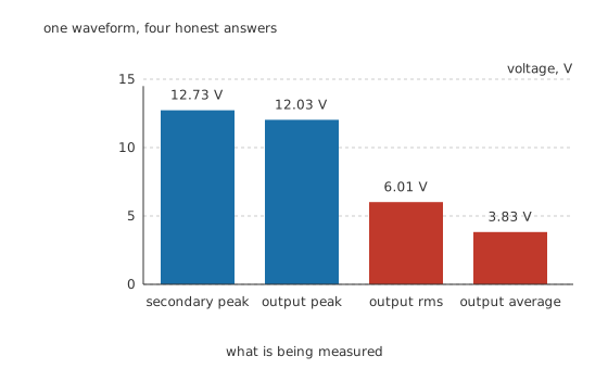
One waveform, four honest answers.
The rms value of the output is 6.01 V, exactly half the output peak, because a half-wave shape is a full sine for half the time and nothing for the rest. Notice that it is well above the average. That gap is the ripple, and it is what the smoothing capacitor exists to close.
Engineer
Where the shape costs you
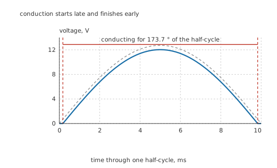
Conduction starts late and finishes early.
The diode does not begin conducting at the zero crossing. It begins when the secondary passes its forward drop and stops again on the way back down, so conduction covers 173.7 ° of the half-cycle rather than the full 180 degrees.
On a 12.73 V peak that shortfall is trivial. On a secondary of a couple of volts it is not, and it is one of two reasons a low-voltage half-wave supply behaves so much worse than the arithmetic suggests. The other is that the fixed drop is a large fraction of a small peak, which the diode lesson works through directly.
How much of the heating is the part you wanted
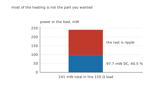
Most of the heating is not the part you wanted.
Worked example — Useful power against total power
The rms output is 6.01 V, so the current is 40.1 mA rms and the load dissipates 241 mW in total.
The DC component alone delivers 3.83 V at 25.5 mA, which is 97.7 mW, or 40.5 % of the total.
Everything else is ripple: real heat in the load, contributing nothing to the steady output the rectifier exists to produce.
That ratio has a standard shorthand. The form factor is the rms value divided by the average, here 1.571, and the ripple factor is the ratio of the ripple's own rms value to the average, here 1.211. A ripple factor above one means the wobble is larger than the thing it is riding on, which is a fair description of what an unsmoothed half-wave output looks like.
What it does to the transformer
The current the secondary supplies flows in one direction only. That is not a small detail: it means the transformer's core carries a net DC magnetisation, which pushes it towards saturation on one half of every cycle and makes it run hotter and noisier than the same load would through a full-wave rectifier. A transformer sized for its rms rating can still be overworked by a half-wave load, and this is why half-wave designs are rare above small currents.
Professional
Choosing the diode, and when to use this at all
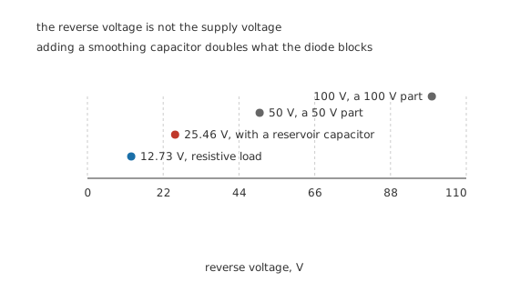
The reverse voltage is not the supply voltage.
The diode's reverse rating is the one selection number people get wrong, and it gets worse the moment the circuit becomes useful.
Into a purely resistive load the worst reverse voltage is the secondary's own peak, 12.73 V. Add a reservoir capacitor, which every practical supply has, and the load side sits near the peak while the secondary swings to the opposite peak. The diode then sees the sum: 25.46 V, twice as much. A 50 V part covers that with real margin and a 100 V part covers it comfortably, and neither costs anything to specify.
The current rating needs the same care in the other direction. Into a resistive load the diode carries the load's average, 25.5 mA. Add the reservoir capacitor and it stops carrying a smooth half-sine and starts carrying a tall narrow spike once per cycle, whose peak can be many times the average. Both of the diode's current ratings have to be checked against that spike rather than against the average, and that is the subject of the smoothing lesson.
When half-wave is the right answer
When the load is tiny and the ripple does not matter. An indicator lamp, a relay coil, a trickle charger. The parts count is one and the ripple is somebody else's problem.
When isolation and simplicity beat efficiency. A capacitive dropper or a small linear supply feeding a few milliamps of logic can be perfectly well served this way, with a large enough reservoir capacitor to bridge the gap.
When the gap is wanted. Some circuits use the gap deliberately: zero-crossing detectors, mains-synchronised timing, and simple battery chargers that need a rest period between charging pulses to measure the cell.
When it is the wrong answer
Any time the transformer is working hard. The DC magnetisation and the poor use of the winding both push the transformer's size up for the same delivered power.
Any time the ripple has to be small. The gap between humps is a full half-cycle, which at 50 Hz is ten milliseconds of nothing. Holding a rail steady across that takes a much larger reservoir capacitor than a full-wave rectifier needs, because full-wave halves the gap.
Any time efficiency is a specification. Only 40.5 % of the heating in the load is useful output before smoothing, and the transformer is being asked for more rms current than the DC it delivers.
The practical conclusion is that half-wave rectification survives at the very small end and at the very cheap end, and everything else has moved to a bridge. Knowing why is more useful than knowing the formula, because the same reasoning decides every rectifier question after this one.
Common mistakes
- Expecting a 9 V secondary to give 9 V of DC — the average of an unsmoothed half-wave output is under four volts, because the peak is divided by pi and the diode takes its drop off the top.
- Sizing the diode's reverse rating from the secondary voltage — into a resistive load it sees the full peak, and with a reservoir capacitor it sees twice the peak.
- Confusing the rms and average values of the output — they differ by the form factor of 1.571 here, and a DC meter and an AC meter will report different numbers for the same waveform.
- Ignoring the DC magnetisation of the transformer — half-wave load current flows one way only, which pushes the core towards saturation and makes a nominally adequate transformer run hot.
- Assuming the diode conducts for the whole half-cycle — it conducts for 173.7 ° here, and on a low-voltage secondary the shortfall becomes a serious loss.
Frequently asked questions
What does a half-wave rectifier do?
It passes the half of each alternating cycle that drives current in one direction and blocks the other half, using a single diode in series with the load. The output is a train of humps separated by gaps, which is unidirectional but far from steady.
What is the average output voltage of a half-wave rectifier?
The peak divided by pi, less the diode's drop. For a 9.0 V rms secondary the peak is 12.73 V, the output peaks at 12.03 V after a 0.70 V drop, and the average over the full cycle is 3.83 V.
What reverse voltage does the diode have to withstand?
Into a resistive load, the full peak of the secondary. With a reservoir capacitor holding the output near the peak, the diode sees the sum of the output and the opposite secondary peak, which is twice the peak. Size the part for the second case even if the first is what you have built today.
Why is a half-wave rectifier bad for the transformer?
Because the secondary current flows in one direction only, so the core carries a net DC magnetisation on top of the alternating flux. That pushes the core closer to saturation on one half of each cycle, increasing losses and heating for the same delivered power.
When would anyone still use half-wave rectification?
Where the load is very small, where cost matters more than efficiency, or where the gap between conduction periods is actually wanted, as in a zero-crossing detector or a charger that measures the cell between pulses. Above a few tens of milliamps a bridge is almost always better.