
Quick Answer
A full-wave rectifier uses both halves of every cycle instead of throwing one away. A bridge of four diodes does it from an ordinary winding at the cost of two diode drops; two diodes on a centre-tapped winding do it with one drop but need twice the winding. Both double the ripple frequency.
Safety
Every figure here is fed from a low-voltage transformer secondary, and every number belongs to that secondary. A bridge rectifier connected directly to the mains, which is what most modern equipment contains, has no isolation: neither of its output rails is safe to earth and neither is safe to clip a probe to. This lesson teaches the topology, not mains-connected practice, and it publishes no figure for a mains-connected circuit.
Intuition
The treadle sewing machine
A treadle sewing machine is worked by rocking a plate with your foot. The plate goes down, then up, then down again, and the motion is symmetrical and useless on its own. What makes the machine work is a crank that takes both halves of the rock and turns them into rotation in one direction. Neither stroke is wasted, and the wheel never hesitates.
That is what a full-wave rectifier does to alternating current. A half-wave rectifier is a machine that only uses the downstroke: half of every cycle drives the load and the other half is discarded, leaving a gap. A full-wave rectifier catches the other half too, turns it round, and sends it through the load in the same direction as the first.
There are two mechanisms for doing this and they are genuinely different machines rather than variations. One uses four diodes arranged so that whichever way the supply leans, two of them route the current the right way through the load. The other splits the winding in half and uses two diodes, one for each half, with the middle of the winding as the return.
They produce almost the same output and they cost quite different things. The four-diode version is cheap on copper and expensive on diode drops. The two-diode version is the opposite. Which of those matters depends entirely on the voltage you are working at, and that trade is the practical content of this lesson.
Practitioner
The bridge
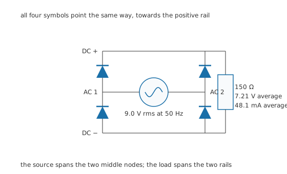
All four symbols point the same way, towards the positive rail.
The four diodes sit in two columns. In each column one diode points from the middle node up to the positive rail, and the other points from the negative rail up to the middle node. Every symbol points the same way, which is the quickest check that a bridge has been drawn or built correctly.
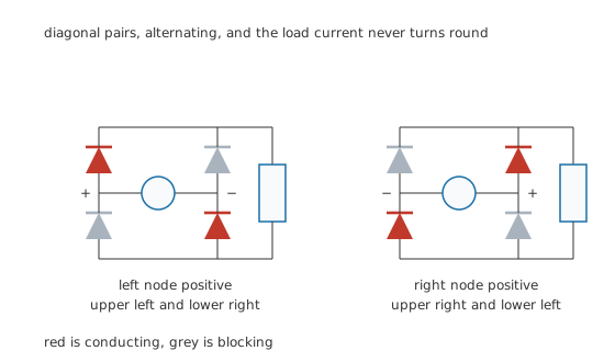
Diagonal pairs, alternating, and the load current never turns round.
Whichever middle node is positive, current leaves it through the diode above it, crosses the load from the top rail to the bottom rail, and returns through the diode below the other middle node. The pairs are diagonal, they alternate, and the load current runs the same way both times.
Worked example — What a bridge delivers from a 9.0 V secondary
The 9.0 V secondary peaks at 12.73 V.
Two diodes are in the path at every instant, so 0.70 V comes off twice and the output peaks at 11.33 V.
With 2.0 conducting half-cycles in each period, the average is 7.21 V, and into 150 Ω that is 48.1 mA.
The same secondary through a half-wave rectifier gave only 3.83 V, so the bridge delivers 1.884 times as much despite paying an extra drop.
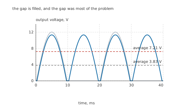
The gap is filled, and the gap was most of the problem.
The other change matters as much as the average. The humps now arrive every 10 ms instead of every 20 ms, so the ripple is at 100 Hz rather than 50 Hz. Twice the frequency and half the gap means a smoothing capacitor has half as long to hold the rail up, which more than halves the capacitance the job needs.
Engineer
The centre-tapped alternative
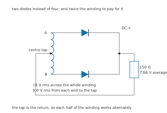
Two diodes instead of four, and twice the winding to pay for it.
Split the winding in half and bring the middle out as a third terminal, and the two ends move in opposite directions at once. Put a diode on each end with both cathodes joined, and whichever end is positive with respect to the tap conducts into the load while the other is reverse biased. The tap is the return.
Worked example — The same output, one drop instead of two
For the load to see the same peak, each half of the winding has to deliver 9.0 V rms, so the whole winding has to be 18 V rms end to end.
Only one diode is ever in the path, so the output peaks at 12.03 V rather than 11.33 V.
The average is 7.66 V, giving 51.0 mA into the same load, a little more than the bridge.
What the choice actually turns on
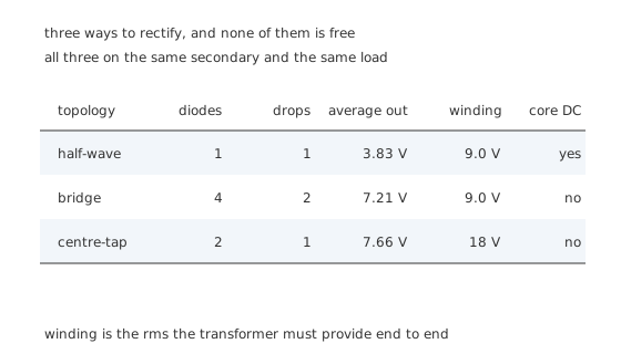
Three ways to rectify, and none of them is free.
The centre-tap wins on drops and loses on copper. Half of a centre-tapped winding sits idle at any instant, so the transformer has to be built for roughly the same power through half the winding at a time, which makes it larger and more expensive than the winding a bridge needs for the same output.
That trade flips with voltage. On a five-volt output, two drops are a quarter of what you have and the centre-tap's advantage is real. On a hundred-volt output, two drops are a rounding error and nobody would pay for the extra winding. This is why almost every modern low-power supply uses a bridge and why centre-tapped rectifiers survive mainly in low-voltage, high-current positions, usually with Schottky diodes to cut the one remaining drop as well.
Where the reverse voltage goes
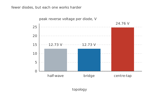
Fewer diodes, but each one works harder.
A bridge diode holds off 12.73 V, the secondary's own peak. A centre-tap diode holds off 24.76 V, because while one half of the winding drives the load through its diode, the blocking diode has the other half of the winding stacked on top of the output it is looking at. Halving the diode count doubles the reverse voltage each one has to survive, and a design that swaps topology without revisiting the rating is a design that fails in service.
Ripple, and how much better it is
Worked example — How much of the load's heat is now useful
The bridge output has an rms value of 8.01 V, so the load dissipates 428 mW.
The DC component alone is 7.21 V at 48.1 mA, which is 347 mW, or 81.1 % of the total.
The form factor here is 1.111 and the ripple factor 0.483, both far better than the half-wave figures, which the half-wave lesson works out for 1.0 conducting half-cycle per period.
Professional
Building one, and what goes wrong
Bridges come as one part. A packaged bridge rectifier has four diodes in a single body with two AC terminals and two DC terminals marked. It is usually cheaper than four discrete diodes, it is impossible to fit one diode backwards, and its thermal path is designed for all four dissipating together. Discrete diodes are worth using when the current is small, when board space is odd, or when you want Schottky parts that no packaged bridge offers.
Dissipation is in the diodes, and there are two of them at once. At 48.1 mA the pair dissipates 67.3 mW, which is nothing here and is the dominant loss in a five-amp supply. A packaged bridge with a tab needs that tab bolted to something.
The transformer no longer sees DC. This is a quiet advantage of both full-wave topologies over half-wave. Current is drawn on both half-cycles, so the core carries no net magnetisation and the transformer can be used at its rating rather than derated.
The three failure modes worth recognising
One diode short in a bridge puts the secondary across two conducting diodes for half of every cycle, which is a short circuit through the transformer. It presents as a blown fuse, a very hot transformer, or both, and the diode is not the obvious suspect.
One diode open in a bridge turns it into a half-wave rectifier. The output falls to roughly half, the ripple doubles and drops back to 50 Hz, and the circuit often still works badly enough to be blamed on something else. A ripple frequency of 50 Hz where 100 Hz was expected is the diagnostic, and it is visible on any scope.
Reverse breakdown on a centre-tap diode is the classic consequence of substituting a part rated for a bridge into a centre-tapped design. The part sees 24.76 V where the bridge part saw 12.73 V, and a part chosen with a comfortable margin in one topology can have none at all in the other.
What has to happen next
Nothing built so far is a power supply. The output is unidirectional but it still swings from 11.33 V down to zero and back 100 Hz times a second, and no circuit that needs a supply rail will tolerate that. Adding a reservoir capacitor changes the shape of everything, including the current the diodes carry, and smoothing capacitors and ripple is where the design actually gets finished. It also changes what the diodes must hold off, which is why the reverse rating chosen here is a starting point rather than an answer.
Common mistakes
- Wiring a bridge with one diode reversed — the two AC nodes end up connected through two conducting diodes for half of every cycle, which shorts the secondary. All four symbols pointing the same way is the check.
- Reusing a bridge's diode rating in a centre-tapped design — the centre-tap diode holds off 24.76 V against the bridge diode's 12.73 V on the same secondary.
- Forgetting that a bridge costs two drops, not one — on a low-voltage output that is a large fraction of what the secondary delivers, and it is the main reason centre-tapped rectifiers persist there.
- Sizing a centre-tapped transformer as if the whole winding worked continuously — each half carries current only on alternate half-cycles, so the winding has to be twice the voltage and is used half the time.
- Missing an open diode in a bridge — the circuit still works, at roughly half the output. The giveaway is the ripple frequency dropping from 100 Hz back to 50 Hz.
Frequently asked questions
How does a bridge rectifier work?
Four diodes are arranged so that each of the two AC input nodes can reach the positive rail through one diode and can be reached from the negative rail through another. Whichever AC node is positive, current flows out of it, through the load from the positive rail to the negative rail, and back into the other AC node, so the load current runs the same way on both half-cycles.
Why is a bridge output lower than a centre-tapped one?
Because two diodes are in the current path at every instant rather than one, so two forward drops come off the peak instead of one. On a 9.0 V rms secondary that is the difference between an 11.33 V peak and a 12.03 V peak, which is small at this voltage and significant on a five-volt output.
Why does full-wave rectification double the ripple frequency?
Because the load now receives a hump on every half-cycle instead of on every other one. From a 50 Hz supply the humps arrive every 10 ms rather than every 20 ms, so the ripple sits at 100 Hz and the smoothing capacitor has half as long to hold the rail up between them.
Which is better, a bridge or a centre-tapped rectifier?
A bridge for almost everything, because the transformer is smaller and the extra diode drop rarely matters. A centre-tap where the output voltage is low enough that saving one drop is worth a bigger transformer, which in practice means low-voltage high-current supplies, usually with Schottky diodes.
How can I tell if one diode in a bridge has failed open?
The output roughly halves and the ripple frequency falls from twice the supply frequency back to the supply frequency, because the circuit has become a half-wave rectifier. That frequency change is visible on a scope and is the fastest diagnostic, since the supply often still limps along well enough to be blamed on something else.