
Quick Answer
A Schottky diode is a junction between metal and lightly doped silicon rather than between two doped silicons. It drops roughly half as much forward and stores no minority charge, so it turns off instantly. In exchange it leaks far more, and it runs out of reverse voltage rating well before an ordinary diode does.
Intuition
The aircraft that turns round without unloading
An airliner that has just landed cannot leave again immediately. Bags have to come off, the cabin has to be cleared, the hold has to be emptied. None of that is flying; it is the unavoidable cost of having carried something. An aircraft with nothing in the hold can turn round in a fraction of the time, because there is nothing to unload.
An ordinary PN diode carries cargo while it conducts. Forward current means carriers are injected across the junction into the region on the other side, and they sit there as long as conduction continues. Reverse the voltage and the diode cannot block until every one of those carriers has been swept back out, which takes real time and real current in the wrong direction.
A Schottky diode has no hold. Its junction is between a metal and lightly doped silicon rather than between p-type and n-type, and that arrangement conducts entirely with the carriers that were already there. Nothing is injected, nothing is stored, and there is nothing to remove. The moment the voltage reverses, it is off.
There is a second, more visible benefit. The barrier a carrier has to cross at a metal-silicon junction is lower than the one at a PN junction, so the forward drop is roughly half. On a five-volt supply that is the difference between losing a useful fraction of the output and losing twice as much.
Neither of those is free, and this lesson is mostly about what they cost.
Practitioner
What the low drop buys
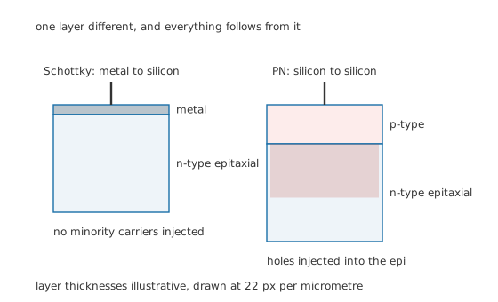
One layer different, and everything follows from it.
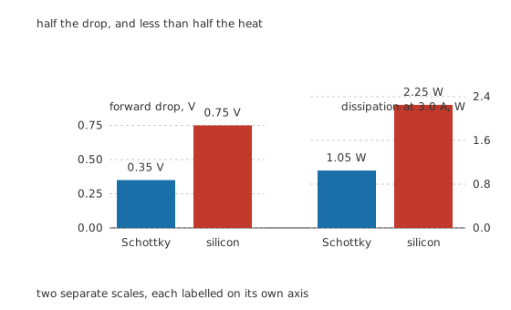
Half the drop, and less than half the heat.
Worked example — What the drop is worth in a 5 V supply
At 3.0 A, a Schottky at 0.35 V dissipates 1.05 W, while a silicon rectifier at 0.75 V dissipates 2.25 W.
The saving is 1.20 W, which is more than a watt out of one component.
The output is 5.0 V at 3.0 A, or 15.0 W. So the rectifier loses 6.54 % of what goes in with the Schottky and 13.0 % with the silicon part.
That ratio is the entire commercial argument. On a five-volt output the rectifier is the largest single loss in the supply, and halving it halves the heatsink and the enclosure temperature with it. On a two-hundred-volt output nobody would notice either part, which is exactly why Schottky diodes are a low-voltage phenomenon.
The drop is not a fixed number any more than an ordinary diode's is. It rises with current, falls as the part warms, and the figures above belong to one operating point.
Engineer
What the absent charge buys
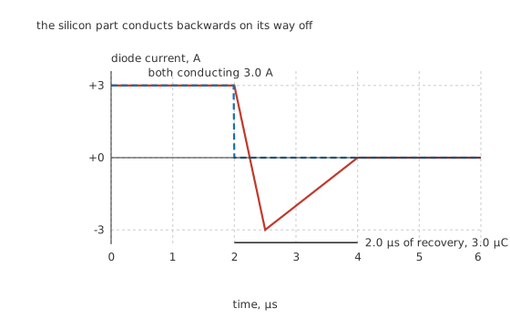
The silicon part conducts backwards on its way off.
When an ordinary diode is switched off, it does not stop. It conducts backwards, at very nearly the current it was carrying forwards, until the stored charge has been swept out. Only then does the junction start to block.
Worked example — How much charge, and what it costs to remove
Take the silicon part's recovery as reaching 3.0 A for 2.0 µs. A rectangle of that height and width would be 6.0 µC; the recovery current is a triangle, so the charge is half of it, 3.0 µC.
All of that charge is pushed through the reverse voltage the circuit is applying, 30 V, so each switch-off dissipates 90 µJ.
At 100 kHz, that is 9.0 W of loss, against a conduction loss of only 2.25 W.
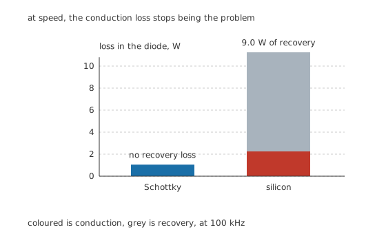
At speed, the conduction loss stops being the problem.
The switching loss overwhelms the conduction loss by a factor of four, and this is the honest reason ordinary rectifiers are not used in switching supplies. It is not that they are slightly worse; it is that the loss mechanism that dominates at speed does not exist for them at fifty hertz and is the only thing that matters at a hundred kilohertz.
There is a second consequence that is easy to miss. 2.0 µs out of a 10 µs switching period is 20.0 % of the cycle spent conducting the wrong way, which is not a small perturbation on the waveform. It also injects a burst of current with very fast edges into the circuit, which is a serious emissions problem, and it stresses whatever transistor is doing the switching.
Professional
What it costs
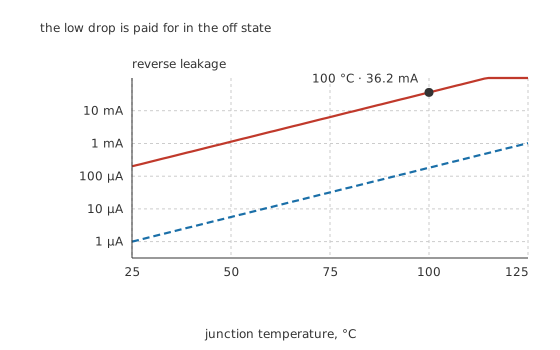
The low drop is paid for in the off state.
Leakage is the first price, and it is a large one. The same low barrier that lets carriers across easily in the forward direction lets them across in the reverse direction too. This part leaks 200 µA at 25 °C against a silicon part's 1.0 µA, a factor of 200.
Worked example — Leakage at temperature, and the runaway it can start
Leakage roughly doubles every ten degrees, so over 75 °C it multiplies by well over a hundred and reaches 36.2 mA at 100 °C.
Against 30 V of reverse voltage that is 1.09 W of dissipation produced while the diode is supposed to be doing nothing.
That heating raises the junction temperature, which raises the leakage, which raises the heating. A Schottky run hot near its reverse rating can run away and destroy itself, and no ordinary silicon rectifier does that.
The practical rule is to derate the reverse voltage generously and to think about the leakage at the junction temperature the part will actually reach, not at the temperature on the datasheet's headline.
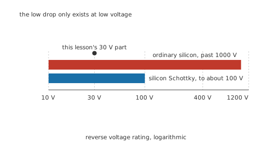
The low drop only exists at low voltage.
The voltage ceiling is the second price, and it is structural. Holding off more reverse voltage means a thicker, more lightly doped drift region, and that region's resistance appears in series with the junction. Push a silicon Schottky much past 100 V and the extra series resistance costs more forward drop than the low barrier saved. Ordinary silicon rectifiers pass 1000 V without difficulty.
Silicon carbide changes that arithmetic, because the material holds off far more field per micrometre, and silicon carbide Schottky diodes are available at hundreds of volts with no stored charge at all. They cost several times what a silicon part does, which is why they appear where the switching loss is worth the money and nowhere else.
Where to use one, and where not to
Use one in any low-voltage rectifier, mains-frequency or switching. The drop saving is real at five volts and the recovery saving is decisive above a few kilohertz.
Use one as a clamp across a switching transistor or in an inductive path, where the recovery of an ordinary diode would appear as a current spike in something that cannot take it. That is why flyback diodes in fast circuits are Schottkys.
Do not use one where the reverse voltage is high, and check the derating rather than the headline number.
Do not use one in a high-impedance or low-current circuit, where the leakage is a signal in its own right. A microamp of leakage into a megohm is a volt.
Do not use one where the junction will be hot and reverse-biased at once. That combination is where the runaway lives, and it is the failure mode a substitution most often introduces.
One habit worth having
When substituting a Schottky for a silicon rectifier, check three things and not one: the reverse rating with real derating, the leakage at the highest junction temperature the design allows, and whether anything downstream depended on the higher forward drop. That last one catches people out in polarity-protection and diode-OR positions, where a lower drop can leave a downstream part with more voltage than it expected.
Common mistakes
- Substituting a Schottky on drop alone — it also leaks two hundred times as much, and its reverse rating is a fraction of what the silicon part offered.
- Using an ordinary rectifier in a switching supply — at 100 kHz its recovery costs 9.0 W against 2.25 W of conduction, so the loss that matters is the one that does not exist at mains frequency.
- Ignoring leakage at temperature — 200 µA at 25 °C becomes 36.2 mA at 100 °C, which at 30 V is over a watt of heating in a part that is supposed to be off.
- Running a Schottky hot and close to its reverse rating — leakage heats the junction, which raises the leakage, and the part can run away.
- Expecting a silicon Schottky above about 100 V — the drift region needed to hold off more voltage adds enough series resistance to cancel the advantage.
Frequently asked questions
What is a Schottky diode?
A diode whose junction is between a metal and lightly doped semiconductor rather than between p-type and n-type material. That gives it a lower barrier, so a lower forward drop, and it conducts entirely with the carriers already present, so it stores no charge and switches off instantly.
Why does a Schottky diode switch faster?
Because there is nothing to clear out. An ordinary diode injects carriers across its junction while conducting, and it cannot block until those have been swept back, which means conducting backwards for a while. A Schottky never injected any, so it stops the moment the voltage reverses.
Can I always replace a silicon diode with a Schottky?
No. Check the reverse rating first, because Schottkys are usually rated far lower. Check the leakage at the real junction temperature, because it is orders of magnitude higher and doubles every ten degrees. And check whether anything relied on the higher forward drop, which polarity protection and diode-OR circuits sometimes do.
Why do Schottky diodes leak so much?
The same low barrier that makes forward conduction easy makes reverse conduction easier too. Leakage is set by how easily carriers get over the barrier, and lowering it helps both directions. That is a direct trade, not a manufacturing shortcoming, and it is why very low drop parts leak most.
Why are silicon Schottky diodes limited to around a hundred volts?
Because holding off more reverse voltage needs a thicker, more lightly doped drift region, and that region's resistance appears in series with the junction. Past roughly a hundred volts the extra resistance costs more forward drop than the low barrier saved. Silicon carbide changes the arithmetic and reaches much higher.