
Quick Answer
An inductor's current cannot change instantly, so opening a switch in series with a coil produces whatever voltage is needed to keep it flowing. A diode across the coil, reverse biased in normal operation, gives that current a loop to circulate in instead, at the cost of a slow release.
Intuition
The catcher on the trapeze
A trapeze artist who lets go is committed. Nothing about the release is negotiable and nothing stops mid-air. Either somebody is there with their hands out at exactly the right moment, or the flyer arrives somewhere nobody planned.
An inductor carrying current is in that position every time a switch opens. Current through a coil is stored energy, and stored energy does not vanish because a contact separated. The coil's response to being interrupted is to develop whatever voltage is required to keep its current going, and if nothing sensible offers a path, that voltage rises until something breaks down and provides one.
The number involved is not a small one. A modest relay coil interrupted quickly demands tens of kilovolts, and what actually happens is that the switch arcs, or the transistor driving it avalanches, and the energy goes through that instead. Both of those destroy the switch, slowly if you are lucky and immediately if you are not.
A flyback diode, also called a freewheeling or catch diode, is the pair of hands. It sits across the coil, does nothing at all while the circuit is running normally, and the instant the switch opens it offers the coil's current a loop of its own to circulate in. The current then decays gently instead of being interrupted, and nothing has to break down.
Practitioner
The loop, and the orientation that makes it one
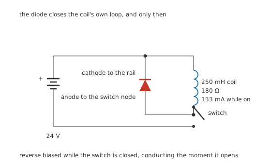
The diode closes the coil's own loop, and only then.
The diode goes across the coil, not across the switch and not in series with anything. Its cathode goes to the more positive end of the coil and its anode to the switch node.
That orientation is the whole design, and it is worth stating what each state does. With the switch closed, the coil's top is on the supply rail and its bottom is near ground, so the diode has the entire supply against it in reverse and carries nothing. When the switch opens, the coil pulls its bottom end upward until it is one diode drop above the rail, at which point the diode conducts and the current circulates through coil and diode alone, with the supply and the switch outside the loop.
Fitted the other way round, the diode would be forward biased by the supply the moment power was applied, and would short the rail through the coil. That is a single reversed component turning a protection circuit into a fault.
Worked example — What the coil is holding
A 250 mH coil of 180 Ω on a 24 V rail settles at 133 mA, reaching it with a time constant of 1.39 ms.
At that current the field holds 2.22 mJ.
That is the energy which has to go somewhere when the switch opens, and it is the same energy however the release is arranged.
Worked example — What the coil demands if nothing catches it
Interrupt 133 mA in 1.0 µs and the coil demands 33.3 kV.
Nothing in the circuit can supply that, so what really happens is that something breaks down first and passes the current anyway. The number is not a prediction; it is a demonstration that the question is badly posed. An inductor's current is not something a switch gets to decide about.
Engineer
What the clamp voltage buys and costs
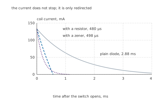
The current does not stop; it is only redirected.
A plain diode is the gentlest possible catch, and gentleness has a cost.
Worked example — How long a plain diode takes to let go
With only the diode's 0.70 V across the coil, the clamp is 0.70 V and the current decays through the coil's own resistance.
It takes 2.88 ms to fall to a tenth of 133 mA, which is roughly twice the coil's 1.39 ms time constant.
For a relay, that is the contacts staying closed for nearly three milliseconds after the drive was removed, and it is a real and often unwelcome delay.
The way to release faster is to let the coil develop more voltage while it does. The current has to fall from its starting value to zero, and the rate at which it falls is the clamping voltage divided by the inductance, so a higher clamp is a faster release. That is a direct trade and there is no way around it.
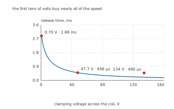
The first tens of volts buy nearly all of the speed.
Worked example — Two ways to raise the clamp
Put 1.0 kΩ in series with the diode and the clamp starts at 134 V, falling as the current does. Release takes 480 µs.
Put a 47 V zener in series with the diode instead and the clamp is a fixed 47.7 V all the way down. Release takes 498 µs.
Either is about 5.79 times faster than the plain diode, and both are paid for by the switch.
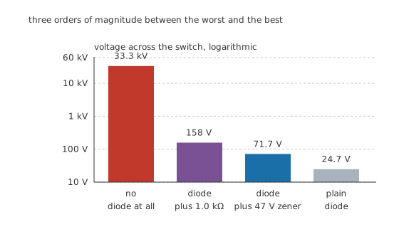
Three orders of magnitude between the worst and the best.
The switch sees the supply plus the clamp. A plain diode leaves it at 24.7 V, barely above the rail. The resistor takes it to 158 V and the zener to 71.7 V, both of which have to be inside whatever the switching device can survive.
The zener is the better of the two for one specific reason. Its clamp does not depend on the current, so the peak voltage is the same whether the coil was carrying its full current or a fraction of it. A series resistor's clamp is proportional to the current at the instant of switch-off, so a circuit that switches at varying currents sees a varying peak, and the worst case is the one that has to be designed for.
Professional
Where the energy goes, and the details that bite
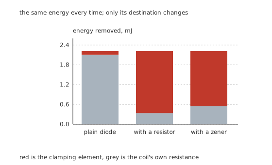
The same energy every time; only its destination changes.
Worked example — The energy split in the three cases
With a plain diode the clamping path takes only 116 µJ and the coil's own winding absorbs 2.11 mJ, because the diode's drop is tiny beside the winding's.
With 1.0 kΩ in series the resistor takes 1.89 mJ and the winding 336 µJ.
With the zener the clamp takes 1.68 mJ and the winding 544 µJ.
The total is always 2.22 mJ, because it was in the field before any of this was decided.
That last sentence is the reason people size these components wrongly. On a relay switched once an hour, a millijoule is nothing at all. On a coil switched at a kilohertz, the same millijoule arrives a thousand times a second and the clamping element has to lose watts. The energy per event is a property of the coil; the power is a property of how often you switch it.
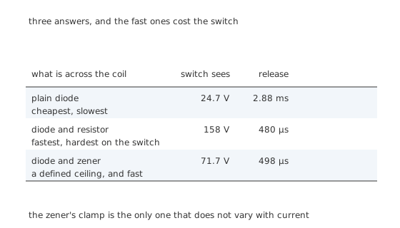
Three answers, and the fast ones cost the switch.
Five things to get right
Put it close to the coil. The loop the current circulates in is the coil, the diode and the wiring between them, and that wiring's inductance is in the loop too. A diode on the other side of a board leaves a metre of wire in a path carrying amps that change in nanoseconds, and the voltage that develops across it is exactly what the diode was fitted to prevent.
Rate it for the coil's full current, not for the average. The diode carries the whole coil current the instant the switch opens, and its average is only low because the duty is. Both of the diode's current ratings apply.
Use a fast diode where the switching is fast. An ordinary rectifier's reverse recovery means it conducts backwards for a moment every time the switch closes again, which puts a current spike through the switching device. A Schottky or a fast-recovery part removes that.
Check the reverse rating against the supply, and against the clamp. The diode holds off the supply voltage in normal operation. If a zener is in series with it, the pair holds off the supply and the clamp is on the other side of it, so the arrangement has to be worked through rather than assumed.
Expect the release delay, and design for it. A relay released through a plain diode drops out measurably later than one released without. Where the timing matters, the answer is a zener in series, and where it does not, the plain diode is cheaper and easier on the switch.
Two places this appears without being called a flyback diode
Across every winding, everywhere. Motors, solenoids, contactors, transformer primaries and the coil in an ignition system are all inductors being switched, and they all need the same provision.
Inside every switching regulator. A buck converter's catch diode is doing precisely this: catching the inductor's current when the switch turns off, and handing it back when the switch turns on. There it conducts for most of every cycle rather than briefly, which is why the drop matters and why Schottky diodes are almost universal in that position.
Common mistakes
- Fitting the diode the wrong way round — the cathode goes to the more positive end of the coil. Reversed, it is forward biased by the supply and shorts the rail through the coil the moment power is applied.
- Putting the diode across the switch instead of across the coil — the coil's current then has no loop, and the diode conducts the supply instead.
- Forgetting the release delay — with a plain diode this coil takes 2.88 ms to fall to a tenth of its current, which is a real delay in a relay's drop-out time.
- Mounting the diode far from the coil — the wiring between them is in the loop, and its inductance develops the very voltage the diode was fitted to prevent.
- Sizing the clamping element on energy per event alone — the energy is fixed by the coil, but the power is the energy multiplied by the switching rate, and a fast-switching circuit needs a part that can lose watts.
Frequently asked questions
Why does opening a switch on a coil produce a high voltage?
Because the current through an inductor cannot change instantly, and the coil develops whatever voltage is needed to keep it flowing. Interrupting 133 mA in a microsecond on a 250 mH coil demands tens of kilovolts, so in practice something breaks down and passes the current instead.
Which way round does a flyback diode go?
Across the coil, with its cathode on the more positive end and its anode on the switched end. That leaves it reverse biased by the supply while the circuit is running, and forward biased the moment the coil pulls the switched end above the rail.
Why does a plain flyback diode make a relay slow to release?
Because it leaves only its own 0.70 V across the coil, so the current decays through the coil's own resistance and takes about two time constants to fall to a tenth. Here that is 2.88 ms. Raising the clamping voltage speeds it up in direct proportion.
Is a zener better than a resistor in series with the diode?
Usually, for one reason: the zener's clamping voltage does not depend on the coil current, so the peak the switch sees is the same whatever the current was at switch-off. A series resistor's clamp is proportional to that current, so a circuit switching at varying currents sees a varying and less predictable peak.
Does the flyback diode need to be a fast one?
For a relay switched occasionally, no. For anything switching quickly or repeatedly, yes: an ordinary rectifier's reverse recovery means it conducts backwards briefly every time the switch closes again, putting a current spike through the switching device. A Schottky or fast-recovery part avoids that.