
A relay coil needs more current than a logic pin can supply, so a transistor switches it. The coil's stored energy has to be given a path at turn-off, or it appears across the transistor as a destructive voltage — which is what the clamp diode is for.
Intuition
The coil does not stop when you tell it to
Switching a relay looks like the easiest thing in electronics. A logic pin goes high, a transistor turns on, a coil is energised, contacts move. Four components and no subtlety.
It is easy, and it is one of the most reliably botched circuits there is, because of one thing: a coil carrying current does not stop carrying it when you take the drive away.
Turn the transistor off and the coil still has current in it, and current in a coil is energy in a magnetic field. The coil's entire character is that it resists changes in its current, and you have just asked for the most abrupt change possible. It responds by generating whatever voltage it takes to keep the current going — and if nothing will let the current through, "whatever it takes" is however many volts the transistor can stand before it breaks down.
So the transistor gets the whole of the coil's stored energy dumped into a small piece of silicon, every single time the relay is switched off. Sometimes it survives. Sometimes it survives a few thousand times and then does not, which is worse, because the fault appears months after the design was signed off.
The cure is one diode, fitted one particular way round. Fitted the other way round it shorts the supply. There is no version of this circuit where the diode's orientation is a matter of taste, and that is why this lesson exists.
Safety
Two hazards, and only one of them is about the driver. The first is the one this lesson computes: without a clamp the coil drives the collector to whatever the transistor breaks down at — an illustrative 40 V here against the 12.7 V a diode allows — and puts the coil's 139 µJ into the junction at every turn-off. That destroys transistors, and it does it slowly enough to look like a mysterious field failure. The second is the one that hurts people, and it is on the other side of the relay. If the contacts are switching mains, the contact side is lethal whenever the equipment is plugged in, regardless of what the coil is doing, and a normally-closed contact is connected when the coil is off. The low-voltage side gives no indication of any of this. Fitting the clamp diode backwards is the specific mistake to watch for. Reversed, it is forward-biased from the supply rail straight through to the collector the moment power is applied: the supply is shorted through the diode and the transistor, and depending on what fails first the result is a destroyed transistor, a destroyed diode, a blown track or a fire. It also looks almost identical on a schematic and passes every automated check. Every number here is an explicitly invented illustration — the transistor's gain, saturation voltage, breakdown and leakage, and the diode's forward drop are not any real part's ratings.
Practitioner
Four components, and one of them has an orientation
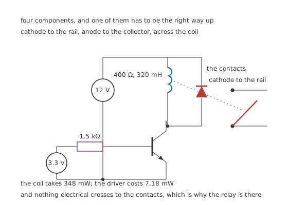
Cathode to the rail, anode to the collector, across the coil.
The relay is the one the previous lesson describes: a 12 V coil of 400 Ω and 320 mH, letting go below 9.0 mA.
Worked example — What the transistor has to do
With the transistor saturated at an illustrative 0.20 V, the coil takes 29.5 mA and dissipates 348 mW.
A transistor whose gain is only guaranteed to 50 needs at least 590 µA of base current to carry that.
The driver itself costs almost nothing: 1.28 mW at the base and 5.90 mW in the collector, 7.18 mW in total against the coil's 348 mW.
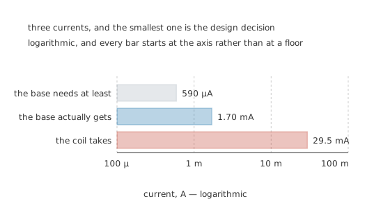
Logarithmic, and every bar starts at the axis rather than at a floor.
Design against the minimum gain, not the typical one. A datasheet's typical gain is a description of a production batch; its minimum is the promise. A driver designed on the typical figure works on the bench and fails on the units at the bottom of the distribution, which is the same failure mode as designing on the wrong end of any other tolerance.
The transistor has to reach saturation, and reaching it is the design job. A transistor part-way on has volts across it and current through it, which is watts, and a driver is sized so that cannot happen.
The coil is not a resistor, and the driver has to survive both facts about it. For the steady state it behaves as 400 Ω and nothing else matters. For the microsecond after turn-off it behaves as 320 mH and nothing else matters. Every problem in this circuit comes from designing for the first and forgetting the second, and the fourth layer is about the component that reconciles them.
Engineer
Choosing the base resistor
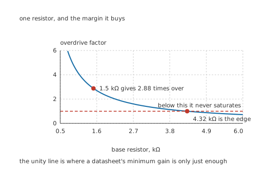
The unity line is where a datasheet's minimum gain is only just enough.
Worked example — One resistor, and the margin it buys
The base sees the logic swing less the base-emitter drop: 3.3 V minus 0.75 V, across whatever resistor you fit.
At the largest resistor that still saturates the device, 4.32 kΩ, the base gets exactly 590 µA and the overdrive is one. That is not a design, it is an edge.
Choosing 1.5 kΩ instead gives 1.70 mA, a forced gain of 17.4 and an overdrive of 2.88. That is the margin a driver wants: enough that the transistor stays saturated whatever the gain, the temperature and the supply do.
The same resistor behaves differently on a different logic rail. Move the drive from 3.3 V to 5.0 V and the same 1.5 kΩ supplies 2.83 mA, an overdrive of 4.80. That is generally welcome, and it is also a reminder that a circuit copied from a five-volt design onto a three-volt one has lost a third of its base drive without anything on the schematic changing.
Off has to mean off. A saturated transistor is easy; a properly off one needs checking too. An illustrative leakage of 1.0 µA against the relay's 9.0 mA drop-out current is a margin of 9000 times, so the relay certainly releases. Where that goes wrong is a floating base: a base resistor with nothing driving it leaves the transistor's state to whatever noise arrives, and a pull-down resistor at the base costs one component and settles it.
More overdrive is not free. A deeply saturated bipolar transistor stores charge in its base and takes longer to turn off — storage time — which for a relay switching a few times a second is irrelevant, and for anything switching fast is the whole problem. A MOSFET avoids it entirely and needs no base current at all, which is why most modern relay drivers use one.
Professional
The diode, and which way up it goes
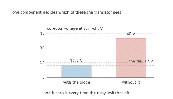
One component decides which of these the transistor sees.
Worked example — What the clamp is worth
At 29.5 mA the coil holds 139 µJ.
With the diode fitted, the current at turn-off continues round a loop of coil and diode, so the collector rises only to 12 V plus the diode's 0.70 V — 12.7 V — and the current decays with the coil's own 800 µs.
Without it the collector rises until the transistor breaks down, at an illustrative 40 V, which is 3.15 times as high and puts the whole 139 µJ into the junction every time.
Now the orientation, because it is the point. The diode goes across the coil, with its cathode on the supply rail and its anode on the collector.
Walk it in both states and the reason is obvious. With the transistor on, the collector is near ground and the rail is at 12 V, so the diode has the whole supply across it backwards and carries nothing. With the transistor off and no current in the coil, both its ends are at the rail and the diode has nothing across it. It conducts in exactly one circumstance: the instant after turn-off, when the coil drags the collector above the rail.
Reversed, it is forward-biased from the rail to the collector as soon as power is applied. That is a short circuit through the diode and the transistor, present continuously, from the moment the board is switched on.
A plain diode is not always the right clamp. It gives the lowest collector voltage and the slowest release, because the current has only the coil's own resistance to decay through — the relay lesson computes what that costs in release time and contact life. A diode in series with a zener, or with a resistor, lets the collector rise higher and gets the current down faster. The choice is between protecting the transistor as hard as possible and letting the contacts open as fast as possible, and it is a real trade rather than an oversight.
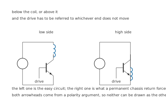
The drive has to be referred to whichever end does not move.
Low side unless something forces otherwise. With the coil hanging from the rail and the transistor pulling its lower end down, the drive is referred to the same ground the logic uses and everything is simple. High-side switching — the transistor between the rail and the coil — is needed when the coil's return has to be permanently connected, and it costs a drive circuit referred to the rail instead of to ground.
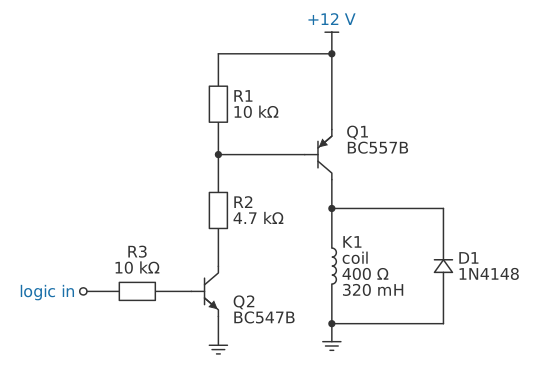
With the same coil, that drive circuit is two transistors. The logic switches a BC547B through 10 kΩ, the BC547B pulls a BC557B's base down through 4.7 kΩ, and 10 kΩ from base to emitter holds the BC557B off the rest of the time. Its base gets 2.28 mA, 3.86 times what a 29.5 mA coil current needs at the minimum gain. The diode still goes across the coil, cathode to the end the transistor drives, which here puts its anode on the return.
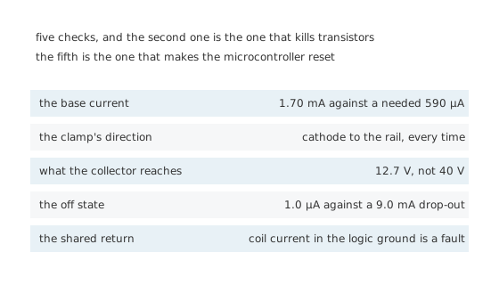
The second is the one that kills transistors; the fifth is the one that makes the microcontroller reset.
Keep the coil's return current out of the logic ground. 29.5 mA switching on and off through a shared ground track puts a voltage step on the logic's own reference, and the symptom is a microcontroller that resets when the relay operates. The cure is layout: the coil's return goes back to the supply separately from the logic's.
A relay driver is available as one part. Arrays of Darlington drivers with the clamp diodes built in exist precisely because this circuit is repeated so often and got wrong so often, and using one removes the orientation question entirely.
Common mistakes
- Leaving out the clamp diode — the collector goes to an illustrative 40 V instead of 12.7 V, 3.15 times as high, with the coil's 139 µJ into the junction at every turn-off.
- Fitting the clamp backwards — cathode to the collector means the diode is forward-biased from the rail the moment power is applied, which is a short circuit through the diode and the transistor.
- Putting the clamp across the transistor instead of across the coil — it protects nothing there, and one way round it shorts the supply.
- Designing on the typical gain — with a minimum of 50 the base needs 590 µA, and a resistor larger than 4.32 kΩ takes the transistor out of saturation altogether.
- Copying a 5 V driver onto a 3.3 V rail — the same 1.5 kΩ goes from 2.83 mA to 1.70 mA of base drive, and the overdrive from 4.80 to 2.88, with nothing on the schematic changing.
- Sharing the coil's return with the logic ground — 29.5 mA switching on and off through a shared track steps the logic's own reference, and the symptom is an unexplained reset.
Parts used in this topic
Frequently asked questions
Which way round does the flyback diode go?
Cathode to the supply rail, anode to the collector, connected across the coil. With the transistor on it then has the whole supply across it backwards and carries nothing; it conducts only in the instant after turn-off, when the coil drags the collector above the rail. Reversed it shorts the supply as soon as power is applied.
What happens if I leave the diode out?
The coil raises the collector until the transistor breaks down — an illustrative 40 V here against the 12.7 V a diode allows, 3.15 times as much — and the coil's 139 µJ goes into the junction. It often survives, for a while, which is what makes the eventual failure so hard to diagnose.
How do I choose the base resistor?
From the minimum gain, not the typical one. The coil takes 29.5 mA, so a transistor guaranteed to 50 needs 590 µA of base drive, which sets the largest usable resistor at 4.32 kΩ. Choosing 1.5 kΩ gives 1.70 mA, a forced gain of 17.4 and an overdrive of 2.88 — margin against gain, temperature and supply variation.
Does the diode have any downside?
It slows the release, because the coil's current then decays through the coil's own 400 Ω with an 800 µs time constant. A zener or resistor in series with the diode lets the collector rise higher and gets the current down faster, at the cost of a higher voltage on the transistor. That is a real trade between transistor protection and contact life.
Why does my microcontroller reset when the relay switches?
Most likely because the coil's 29.5 mA is returning through the same ground track as the logic. Switching it on and off puts a voltage step on the logic's own reference. Route the coil's return to the supply separately from the logic's.
Knowledge check
A 12 V relay coil of 400 Ω is switched by a transistor with a minimum gain of 50 and a saturation voltage of 0.20 V. What base current does it need? (Show answer)
Which way round does the clamp diode go, and why? (Show answer)
What does the clamp save the transistor from? (Show answer)
What changes if the same driver is moved from a 5.0 V logic rail to a 3.3 V one? (Show answer)
How do you check that the driver's off state is really off? (Show answer)
One email a month from the bench
New circuits, lessons, part guides and calculators, on the first Sunday of each month.