
Quick Answer
A relay is a set of switch contacts moved by an electromagnet instead of a finger. The coil and the contacts share no electrical connection, so a small circuit can control a large one without the two touching, and that isolation is usually the point.
Intuition
A switch with its finger somewhere else
A switch needs somebody to press it. That is fine when a person is standing there, and useless when the thing that has decided to switch is a program.
A relay is the same switch with an electromagnet where the finger was. Energise a coil, a piece of iron is pulled towards it, and the piece of iron drags a contact from one place to another. Turn the coil off and a spring takes it back.
What makes that worth doing is not the automation. It is what the arrangement does not have.
The coil is one circuit. The contacts are another. Between them is a mechanical link and nothing else — no shared wire, no shared return, no common ground. The two circuits are as electrically separate as two circuits in different buildings, and the only thing passing between them is a bar of metal moving a fraction of a millimetre.
That means a few milliamps from a microcontroller can switch a mains-powered heater, with the microcontroller's ground and the mains having no connection at all. Semiconductors have got very good at switching things, and most of them cannot do that.
The price is that a relay is machinery. It takes milliseconds rather than nanoseconds, it wears out after a finite number of operations, its coil draws current the whole time it is on, and it makes an audible click. Every one of those is a real limitation, and none of them is the reason people usually reject it.
Safety
The contact side of a relay switching mains is lethal, and it is lethal while the low-voltage side looks completely harmless. That is the hazard the isolation creates as well as the one it solves: a board where the logic is at a safe potential can have contacts a centimetre away at mains, and nothing about the low-voltage side warns you. Treat the whole contact side as live whenever the equipment is plugged in, including with the relay de-energised — a relay's normally-closed contact is connected when the coil is off, which is the opposite of what most people assume when they say a circuit is "off". The isolation is a property of the relay's construction, not of the schematic. Creepage and clearance distances, the coil-to-contact isolation voltage and the approvals that certify them are standard-attached, part-specific, and are not published here in any form; a relay for mains switching has to be one built and approved for it, mounted with its specified spacings preserved on the board. Every number in this lesson is an explicitly invented illustration, including the contact duty of 230 V at 5.0 A used to show what a relay's power gain looks like. Contact ratings are part-specific, they differ between alternating and direct current, and a relay switching a motor or a lamp is doing a harder job than the same relay switching a heater.
Practitioner
The coil, and the moment the metal moves
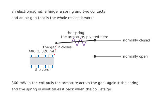
An electromagnet, a hinge, a spring and two contacts — and an air gap that is the whole reason it works.
Worked example — What the coil costs and how fast it fills
Take a 12 V coil of 400 Ω and 320 mH. It settles at 30 mA, drawing 360 mW continuously for as long as the relay is on.
Its time constant is 800 µs, and at the settled current the field holds 144 µJ.
That energy is small, and it is not small enough to ignore. Layer four is largely about where it goes.
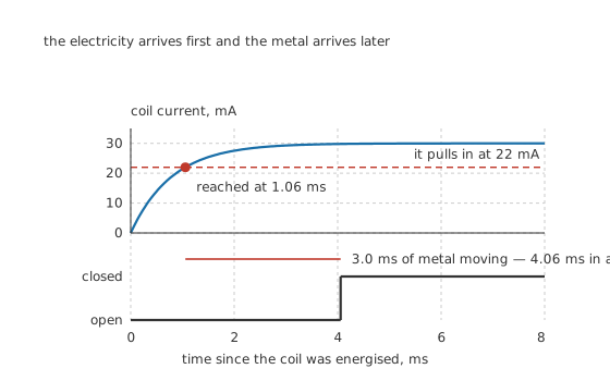
The electricity arrives first and the metal arrives later.
Worked example — Why the relay is slower than its coil
The armature moves when the coil reaches an illustrative 22 mA, which the exponential reaches at 1.06 ms.
Nothing happens at the contacts then. The armature has a gap to cross, which takes a declared 3.0 ms.
So the operate time is 4.06 ms, and three-quarters of it is metal moving. Making the coil faster barely helps; the relay's speed is a mechanical property.
Every figure above is an invented illustration. Coil resistances, pull-in currents and operate times are part-specific and are what a datasheet is for.
The contacts are the contacts from the previous lesson, with all of the same behaviour: they bounce on closing, they arc on opening, they have a resistance, and their rating depends on the load's character as much as its size. An illustrative 50 mΩ contact drops 100 mV and makes 200 mW at 2.0 A.
Engineer
It lets go later than it picks up
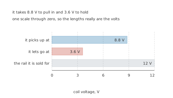
One scale through zero, so the lengths really are the volts.
Worked example — Two thresholds, one coil resistance
The pull-in current of 22 mA through 400 Ω is 8.8 V, which is 0.73 of the nominal rail.
With the armature closed, the air gap has gone, so the magnetic circuit improves and less current holds it there: the drop-out current is 9.0 mA against the 22 mA it took to pick up, which is 3.6 V across the same coil.
That is a hysteresis of 2.44 times, and it is not a defect. It is the closed air gap, and every relay has it.
The hysteresis has two consequences worth carrying.
A relay held in is far cheaper to hold than to operate. Once closed, the coil could be run at a fraction of its rated voltage — which is what an economiser circuit does, dropping the coil to a holding voltage after the first few milliseconds and saving most of the 360 mW. In battery equipment that is worth real money.
A sagging supply keeps a relay closed long past the point where it could pick up. If the load the relay just switched pulls the rail down, the relay stays in at 3.6 V while nothing else on the board works properly. That failure looks like everything else being broken and the relay being fine.
The coil polarity does not matter unless it does. A plain relay coil is just a coil; a relay with an internal diode, an indicator LED or a latching mechanism has a polarity, and fitting it backwards does nothing, or shorts the drive, or blows the LED.
Professional
Where the coil's energy goes, and what that costs
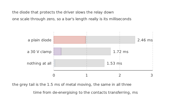
The diode that protects the driver slows the relay down.
Turn the coil off and its 144 µJ has to go somewhere. Left to itself it goes into whatever is switching the coil, at whatever voltage that device breaks down at — which is what a flyback diode is fitted to prevent.
Worked example — Three ways to release, and three release times
A plain diode across the coil lets the current circulate and decay through the coil's own 400 Ω. The current takes until 2.46 ms to fall past the drop-out threshold and let the armature go.
A 30 V clamp forces the current down a straight line instead of an exponential, releasing in 1.72 ms.
With nothing at all, and a switching device that breaks down at an illustrative 200 V, the release is 1.53 ms — 1.61 times quicker than the diode. The diode that saves the driver costs release time, and in every case the last 1.5 ms is metal moving and no clamp can shorten it.
Slower release is not a small matter. The contacts part more slowly, so the arc lasts longer, so the contacts erode faster. A relay clamped with a plain diode can have noticeably shorter contact life than the same relay clamped with a zener or a resistor-diode pair. That trade — driver protection against contact life — is a real design decision that most schematics settle by habit.
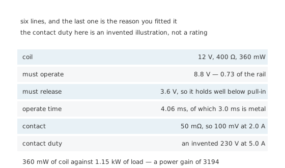
The last one is the reason you fitted it.
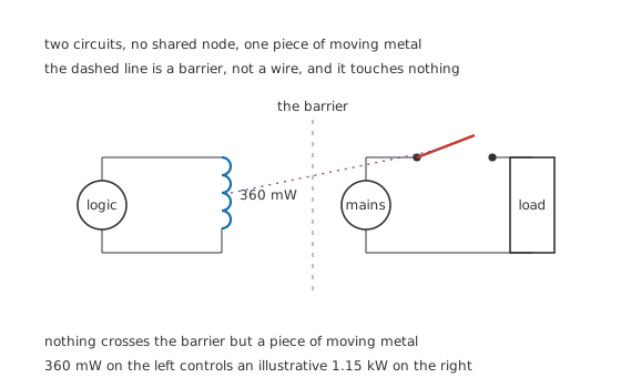
The dashed line is a barrier, not a wire, and it touches nothing.
Worked example — What the isolation buys
The coil takes 360 mW. An illustrative contact duty of 230 V at 5.0 A is 1.15 kW.
That is a power gain of 3194, and it is achieved with no electrical connection whatsoever between the controlling circuit and the controlled one.
A transistor can have far more gain than that. What it cannot have is the gap.
Choosing one
Start with what the contacts have to switch, then the coil. Contact ratings depend on the voltage, on whether it is alternating or direct, on whether the load is resistive, and on how many operations you need. A relay switching a lamp or a motor is doing a much harder job than the same relay switching a heater, because both draw several times their running current at switch-on.
Coil voltage is a range, not a value. It has to operate from the lowest supply voltage the equipment will ever see and survive continuously at the highest, and a coil run above its rating gets hot enough to shift its own resistance and its own thresholds.
Latching relays hold their state with no coil current at all, using a permanent magnet and a pulse to set or reset. For anything battery-powered that is on for hours, the saving over 360 mW continuous is the whole argument.
Reed relays are a different animal. Contacts sealed in a glass tube with an inert atmosphere, operated by a coil around the outside: fast, tiny, good for low-level signals, and rated for very little current.
A solid-state relay does the same job with no moving parts, using an optocoupler and a semiconductor. It switches faster, lasts longer and never bounces, and it leaks when off, drops voltage when on, and needs cooling — which is a different set of compromises, not a better one.
Drive it properly. A relay coil is an inductive load and a logic pin cannot supply 30 mA, so there is a transistor between them, and that transistor needs the clamp this layer is about. Driving relays safely is the next lesson because getting it wrong is common and destructive.
Common mistakes
- Expecting a relay to switch when the coil reaches its threshold — the coil reaches 22 mA at 1.06 ms and the contacts transfer at 4.06 ms, because 3.0 ms of that is the armature travelling.
- Assuming pull-in and drop-out are the same voltage — this relay picks up at 8.8 V and does not let go until 3.6 V, a hysteresis of 2.44 times, so a sagging rail can hold it in long past the point where it could operate.
- Driving the coil from a logic pin — it needs 30 mA at 360 mW, and it is inductive.
- Fitting a plain diode and forgetting what it costs — release goes from 1.53 ms to 2.46 ms, 1.61 times longer, and the contacts arc for all of it.
- Treating a de-energised relay as safe — the normally-closed contact is connected when the coil is off, and on a mains circuit it is live.
- Reading the contact rating as one number — it depends on the voltage, on AC against DC, on the load's character, and on how many operations you need.
Frequently asked questions
Why is a relay slower than its coil's time constant?
Because most of the delay is mechanical. The coil's 800 µs time constant brings it to the 22 mA pull-in threshold at 1.06 ms, but the armature then takes a declared 3.0 ms to cross its gap, so the contacts transfer at 4.06 ms. Making the coil faster barely moves that.
Why does a relay let go at a lower voltage than it picks up at?
Because once the armature is closed the air gap has gone and the magnetic circuit improves, so the holding current falls from 22 mA to 9.0 mA. This one picks up at 8.8 V and releases at 3.6 V — a hysteresis of 2.44 times. It is a property of the geometry, not a fault.
Does the flyback diode do any harm?
It slows the release. With a plain diode the coil current decays through the coil's own 400 Ω, taking 2.46 ms against 1.53 ms with no clamp at all — 1.61 times longer, all of it with the contacts arcing. A zener clamp gets 1.72 ms and still protects the driver.
What is a relay for, when a transistor can switch things too?
The gap. The coil and the contacts share no electrical connection, so 360 mW of logic can control an illustrative 1.15 kW of mains load — a power gain of 3194 — with nothing joining the two circuits. A transistor can beat that gain easily and cannot provide the gap.
Can I reduce the coil power once the relay is closed?
Yes, and that is what an economiser circuit does. The relay holds in down to 3.6 V against the 8.8 V it needed to operate, so after a few milliseconds the coil can be dropped to a holding voltage and most of the 360 mW saved.