
A solid-state relay switches a load with semiconductors instead of contacts, and isolates the control side with light instead of an air gap. Nothing wears out and nothing bounces. In exchange it leaks when off, drops voltage when on, and needs somewhere to put the heat.
Intuition
A relay with nothing to wear out
An electromechanical relay is a good component with one incurable problem: it is machinery. Contacts erode a little on every operation, springs fatigue, and the number of operations left is a finite number that only goes down. For a relay that switches twice a day that is irrelevant. For one that switches every few seconds it is the whole design.
A solid-state relay does the same job with no moving parts at all. The load side is a triac or a pair of thyristors; the control side is an LED. Between them is a transparent insulating layer, and the LED's light is the only thing that crosses it. Send current through the LED and the light falls on a photosensitive gate on the other side, which triggers the output stage. Nothing touches, nothing moves, nothing wears.
There is a second gain that matters more than it first appears. Because there is no armature to fling about, an SSR can be made to wait for a convenient moment before it switches. The convenient moment is the zero crossing, when the supply is passing through nothing on its way from one polarity to the other, and switching then means switching without a step.
Stepping onto an escalator has the same shape. You can step on whenever you like and take your chances, or you can wait the fraction of a second until a step comes level with the floor and get on without a stumble. The wait is real, and it is short, and it costs you nothing you were using.
What you give up is that a semiconductor never fully lets go. A relay's open contact is a gap with air in it; an SSR's off state is a device that still passes a little. That distinction runs through everything below.
Safety
A solid-state relay isolates its control side and isolates nothing else. The load side is at line potential whenever the equipment is connected, exactly as a triac is, and the isolation barrier protects only the low-voltage input. Everything on the output side of the barrier is mains.
"Off" is not off, and this is the one that catches people. A blocking semiconductor still passes leakage — 2.0 mA for the device in this lesson. Across a light enough load that leakage develops most of the supply, so a lamp can glow faintly, a motor can hum, and a circuit that reads as dead on a high-impedance meter can still be lethal. An SSR is not an isolator and must never be used as one. Isolation for maintenance is a mechanical disconnect, a plug, or a lock-off, and nothing else.
Isolation ratings, creepage and clearance distances, and the approvals that certify them are standard-attached, and none of them is published here in any form — including in the cross-section, which is deliberately drawn without a dimension. A part for mains service has to be one built and approved for it, mounted so that its specified spacings survive on the board.
Every device number in this lesson is an invented illustration: the 0.30 transfer ratio, the 2.0 mA gate current, the 1.1 V drop with its 25 mΩ slope, the 1.5 °C/W internal thermal resistance and the 110 °C junction limit. 230 V and 50 Hz are nominal class values.
Practitioner
What crosses the barrier, and what does not
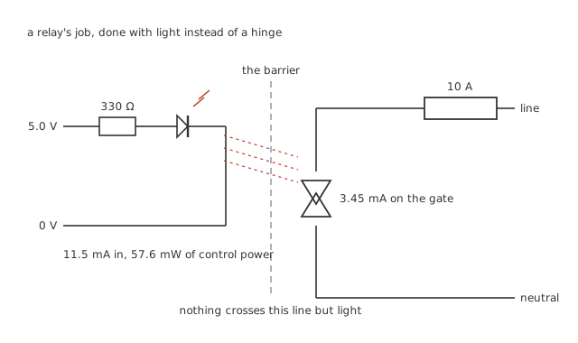
Not one conductor crosses the dashed line. Every wire in the drawing has both ends on the same side of it.
The input is an LED and a resistor, which is the entire interface. That is why an SSR takes a logic output directly where a relay needs a transistor and a flyback diode.
Worked example — From a logic pin to a gate
A 5.0 V output through 330 Ω into an LED dropping 1.2 V gives 11.5 mA, which costs 57.6 mW.
At a transfer ratio of 0.30, the far side of the barrier sees 3.45 mA.
The gate needs 2.0 mA, so there is a margin of 1.73.
For that 57.6 mW the device switches 12.4 W of its own dissipation and a great deal more of load power — a control-to-dissipation ratio of 215, with no electrical connection between the two sides.
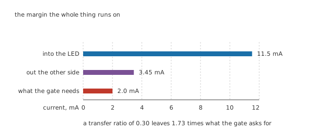
The transfer ratio is legible as a length: the middle bar is 0.30 of the top one.
That margin of 1.73 is the number the whole device runs on, and it is not generous. An LED's output falls with age and falls with temperature, and the transfer ratio falls with it — which is the subject of the optocoupler lesson and the reason a device that worked for five years can start missing operations in the sixth. Designing to the datasheet's minimum transfer ratio at end of life, rather than its typical value when new, is the difference between a product and a prototype.
Two families, and they are not interchangeable
What sits on the far side of the barrier depends entirely on what the relay is for, and the two families share nothing but the input.
An AC relay's output is a triac, or a pair of thyristors back to back. It relies on the load current passing through zero to turn off, which on alternating current it obligingly does a hundred times a second. Put one on a DC supply and it will turn on once and stay on for ever, because nothing ever takes the current away — the failure the thyristor lesson spends a layer on.
A DC relay's output is a MOSFET, or a pair of them source to source. A MOSFET turns off when its gate says so, so the relay works on DC, and because the pair is arranged back to back it can block in both directions rather than conducting through a body diode. It also has no zero crossing to wait for, so a DC relay is always effectively random-fire.
The two look identical from the outside and the packages are often the same, which is why the polarity markings and the AC-or-DC label on the case are the first things to read. A DC relay on AC works badly; an AC relay on DC latches and does not come back.
Engineer
Waiting for the crossing, and what the wait costs
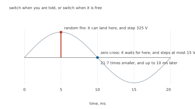
Switch when you are told, or switch when it is free.
A random-fire SSR turns on when the input says so. If that instant happens to be the peak of the sine, the voltage across the load goes from nothing to the peak in the output stage's own turn-on time, and everything the dimmer's fast edge does to the supply happens here too.
A zero-cross SSR does not. It holds the trigger back until the supply is close to a crossing, and only then lets the output stage fire.
Worked example — How small the step becomes, and how long you wait for it
The detector releases the trigger when the line is inside 15 V of zero, which on a 325 V peak is 147 µs either side of the crossing — a window of 294 µs.
The step at turn-on is therefore at most 15 V instead of up to 325 V, which is 21.7 times smaller.
The price is the wait. A crossing arrives every 10 ms, so the delay between the command and the load is anything from nothing to 10 ms, averaging 5.0 ms.
For a heater or a lamp, a delay of a few milliseconds is beneath notice. What is not beneath notice is that the relay can now only deliver whole half cycles.
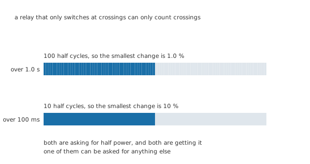
A relay that only switches at crossings can only count crossings.
Worked example — The resolution you are left with
Control the load by switching whole half cycles over a period of 1.0 s and there are 100 of them to play with, so the smallest change available is 1.0 %.
Shorten the control period to 100 ms and there are only 10, so the smallest change becomes 10 %.
Both settings deliver exactly half power. The difference is everything else they could have been asked for.
This is called burst firing or integral cycle control, and it is the natural way to drive a zero-cross SSR. It suits anything with thermal inertia — an oven, a tank heater, an extruder barrel — because the load averages the bursts out and never sees the individual cycles. It suits a lamp badly, because a lamp does not average and the result is visible flicker, and it suits a motor worse.
Professional
The heat, and the current no heatsink can rescue
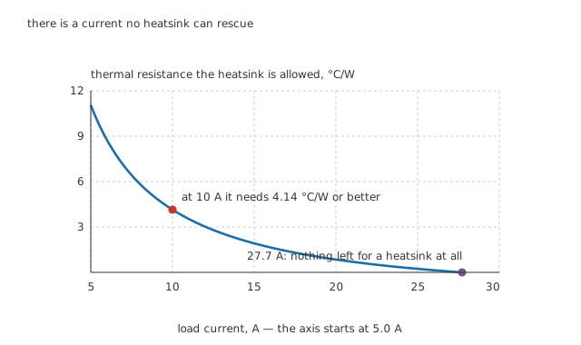
There is a current no heatsink can rescue, and it is closer than it looks.
An SSR's output stage drops around a volt while conducting, and a volt multiplied by the load current is a real amount of heat inside a small plastic body.
Worked example — What the heatsink has to be
At 10 A the stage sees a peak of 14.1 A and an average of 9.00 A, and the two loss terms bill different ones: the 1.1 V threshold costs 9.90 W against the average, and the 25 mΩ of slope costs 2.5 W against the RMS squared. That is 12.4 W in total.
To hold the junction at 110 °C in a 40 °C ambient, everything from junction to air has to come to 5.64 °C/W.
The package spends 1.5 °C/W of that internally, so the heatsink has to be 4.14 °C/W or better.
Now push the current up and watch what happens to that allowance. The dissipation grows faster than the current does, so the total allowed thermal resistance shrinks, and the package's own share does not shrink with it. Eventually the internal resistance alone spends the entire budget.
Worked example — The ceiling
Setting the whole allowance equal to the package's own 1.5 °C/W and solving for the current gives 27.7 A.
That is 2.77 times the working current, and above it no heatsink of any size will keep the junction below 110 °C, because the heat cannot get out of the package fast enough to reach the heatsink in the first place.
This is why a relay's rating falls so sharply with ambient temperature, and why "it is only running at half its rated current" is not the reassurance it sounds like.
It never quite turns off
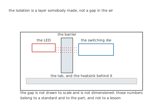
The isolation is a layer somebody made, and the drawing does not dimension it on purpose.
Worked example — What the leakage is worth
Blocking 230 V, the device passes 2.0 mA. That alone is 460 mW dissipated while the relay is supposedly doing nothing.
Treating the leakage as a current source, it develops half the supply across a load of 57.5 kΩ.
So any load lighter than that sits at more than half of line potential with the relay off. A neon indicator glows, a small transformer hums, and a meter reads a voltage that has no business being there.
Choosing between the two kinds of relay
Use a solid-state relay where the switching rate would destroy contacts. Anything cycling every few seconds — temperature control, sequencing, anything under closed-loop control — is where the contact-life argument becomes decisive.
Use an electromechanical relay where the load must actually be disconnected. The gap is the product. An SSR cannot provide it, it leaks when off, and its dominant failure mode is a short rather than an open, which is the wrong way round for a safety function.
Use a random-fire type only when you need the phase. Phase control needs it and nothing else does. Zero-cross is the default because the interference is 21.7 times smaller and the wait is 5.0 ms on average.
Size it by the heat and mount it as though you meant it. 12.4 W needs a heatsink of 4.14 °C/W or better, with thermal compound and a flat surface — heatsinking covers what that means in practice. An SSR bolted to a painted panel is an SSR that will fail.
Check what the load does to it. An inductive load presents the same commutation problem it presents to any triac, which is why SSRs intended for motors are built differently and rated separately, and why snubbers and protection are the next lesson.
Common mistakes
- Treating an SSR as an isolator — it leaks 2.0 mA when off, which develops half the supply across any load above 57.5 kΩ. It is not a disconnect and must never be relied on as one for safety.
- Designing to the typical transfer ratio — the margin here is only 1.73, and the LED's output falls with age and with temperature. Use the datasheet's end-of-life minimum, not its typical value when new.
- Assuming a heatsink can always fix the heat — above 27.7 A the package's own 1.5 °C/W spends the entire allowance and no external heatsink helps at all.
- Using burst firing on a lamp — over 100 ms there are only 10 half cycles, so the resolution is 10 % and the steps are visible as flicker. Burst firing suits loads with thermal inertia and nothing else.
- Fitting a random-fire type by default — it can switch at the peak, stepping 325 V in the output stage's own turn-on time, which is 21.7 times the step a zero-cross type makes.
- Bolting it to whatever is handy — 12.4 W has to leave a small package through one face, and paint, dirt or a warped surface between the tab and the heatsink is a large part of the total thermal resistance.
Frequently asked questions
Can I use a solid-state relay to make a circuit safe to work on?
No. It leaks 2.0 mA when off, which is enough to develop more than half the supply across any load above 57.5 kΩ, and it fails short rather than open. Isolation for maintenance needs a mechanical disconnect that can be seen to be open and locked in that position.
Why does a zero-cross relay cost me control resolution?
Because it can only start and stop at crossings, so it delivers whole half cycles. Over 1.0 s there are 100 of them and the smallest change is 1.0 %; over 100 ms there are only 10 and the smallest change is 10 %. Nothing between two adjacent half-cycle counts can be asked for.
How much drive does the input actually need?
Very little. 5.0 V through 330 Ω into an LED dropping 1.2 V is 11.5 mA and 57.6 mW, which any logic output can supply directly. There is no coil, no inrush and no flyback diode, which is most of why an SSR is easier to drive than a relay.
Why does the rated current fall so fast as it gets hotter?
Because the allowance shrinks from both ends. The dissipation rises faster than the current, so the total thermal resistance the design can afford falls; meanwhile the package's own 1.5 °C/W is fixed. At 27.7 A the internal share alone uses the whole budget, and beyond that the heat cannot get out of the package fast enough for any heatsink to matter.
Is a solid-state relay more efficient than a mechanical one?
No, and by a wide margin. A closed contact drops millivolts; this output stage dissipates 12.4 W carrying 10 A, and all of it has to be got rid of. What an SSR buys is switching rate, silence, speed and the absence of anything that wears out — not efficiency.
Knowledge check
A 5.0 V logic output drives an SSR through 330 Ω into an LED dropping 1.2 V. Does the gate get enough? (Show answer)
What does zero-cross switching buy, and what does it cost? (Show answer)
An SSR carrying 10 A drops 1.1 V plus 25 mΩ. What heatsink does it need to hold the junction at 110 °C in a 40 °C ambient? (Show answer)
Is there a current above which a bigger heatsink stops helping? (Show answer)
Why can a solid-state relay leave a load live when it is switched off? (Show answer)
One email a month from the bench
New circuits, lessons, part guides and calculators, on the first Sunday of each month.