
Interrupting current in a circuit with inductance produces a voltage far larger than the supply, because the loop and the device's own capacitance ring together. A snubber slows that voltage down by adding capacitance; a clamp limits where it stops. They solve different halves of the problem and neither is free.
Intuition
The voltage nobody supplied
Switch a current off and the circuit objects. Every wire has inductance, every inductance resists a change in its current, and the way it resists is by producing whatever voltage it takes to keep the current going. If the switch has just opened, "whatever it takes" can be very large indeed.
That much is familiar from the flyback diode. What is less familiar is what happens when the circuit also has capacitance, which it always does, because the switching device has some across itself whether you wanted it or not. Inductance and capacitance together do not produce a spike that decays; they ring. The voltage overshoots, comes back, overshoots the other way, and does that at a frequency set by the two of them.
A shock absorber is the right picture for the cure. A car's spring on its own would let the body oscillate for a long time after every bump, and the absorber does not make the bump smaller — it converts the motion into heat so that the oscillation stops after one movement instead of ten. A snubber does exactly that to an electrical oscillation, using a resistor for the heat and a capacitor to reach the energy.
There is a second, different cure, and confusing the two is the commonest mistake in this subject. A clamp does not damp anything. It lets the voltage rise at whatever rate it likes and then refuses to let it past a chosen limit, absorbing whatever energy arrives while it holds the line. One changes the slope, the other changes the ceiling.
Most real circuits need both, and every one of them costs something.
Safety
The voltages in this lesson are lethal and they appear in circuits whose supply looks harmless. A 300 V rail is enough to kill on its own, and the ring computed below reaches 1.52 kV — on the same circuit, from the same supply, with nothing having gone wrong. A circuit that measures safe when it is idle can be nowhere near safe while it is switching, and the transients last microseconds, which is far too short for a meter to show and far too long to be harmless.
Do not probe a switching circuit with a grounded oscilloscope probe unless you know the circuit is isolated and you know where its reference sits. Everything the dimmer lesson says about earth clips applies here with a larger voltage behind it.
Stored energy outlives the supply. A snubber capacitor holds 2.12 mJ at the rail voltage and does not discharge when the equipment is switched off, because its own resistor is in series with it and the path may be open. Treat every capacitor in a power circuit as charged until it has been measured, and give it a discharge path in the design.
Every number here is an invented illustration: the 22 µH of loop inductance, the 470 pF of device capacitance, the 800 V blocking rating, the 47 nF and 47 Ω of snubber, the 600 V clamp and the 1.0 µH/m of wiring inductance. Blocking ratings, rate-of-rise ratings and clamping voltages are part-specific and belong to a datasheet.
Practitioner
Nothing failed, and the device saw nearly twice its rating

The rail is 300 V. Nothing in the circuit has failed. This is what the circuit does when it is working.
The loop and the device capacitance form a series resonant circuit, and the current that was flowing in the loop has to go somewhere when the device stops taking it. It goes into the capacitance, and how much voltage that produces depends on a single number: the ratio of the loop's inductance to its capacitance, expressed as an impedance.
Worked example — What the loop is worth as an impedance
With 22 µH and 470 pF, the characteristic impedance is 216 Ω.
Diverting 6.0 A into that impedance adds 216 Ω multiplied by the current on top of the rail, which is a lossless ceiling of 1.60 kV.
The loop has a little resistance in it, so the first peak actually reaches 1.52 kV — a damping ratio of 0.040 costs 6.0 % of the swing. That is still 1.90 times the device's 800 V rating.
The ringing frequency is 1.57 MHz, a period of 639 ns, and the peak arrives 156 ns after the interruption.
Two things about that figure deserve more attention than they usually get.
The device is stressed in both directions. The ring goes as far below zero as it goes above the rail, so a device that only blocks in one direction is being asked to do something it cannot, and the negative half is why so many power devices are sold with a diode already inside them.
None of this is a fault condition. No component is out of specification, no wiring is loose, nothing has degraded. This is the ordinary behaviour of an ordinary circuit interrupting an ordinary current, and if the device is not protected it will not survive its own normal operation.
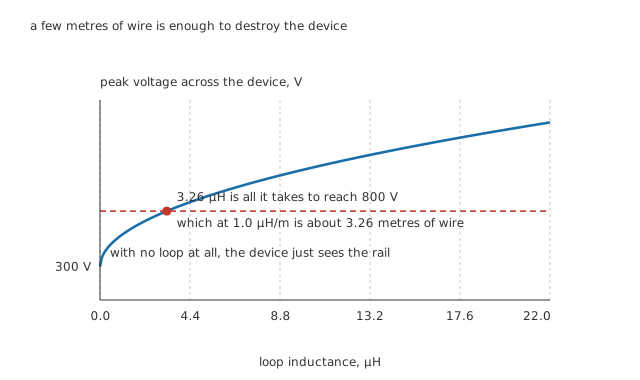
The curve starts at the rail, because with no loop at all there is nothing to ring.
Worked example — How little wiring it takes
Set the peak equal to the device's 800 V rating and solve back for the inductance: 3.26 µH.
At a declared 1.0 µH/m, that is about 3.26 metres of wire in the loop, out and back.
The circuit in this lesson has 22 µH, which is several times that, and it is not an unusual amount for a layout that nobody thought about.
That is why layout is the first line of protection and not a detail to be tidied afterwards. Every centimetre you remove from the switching loop removes voltage from the device, and it costs nothing.
Engineer
What a snubber actually does
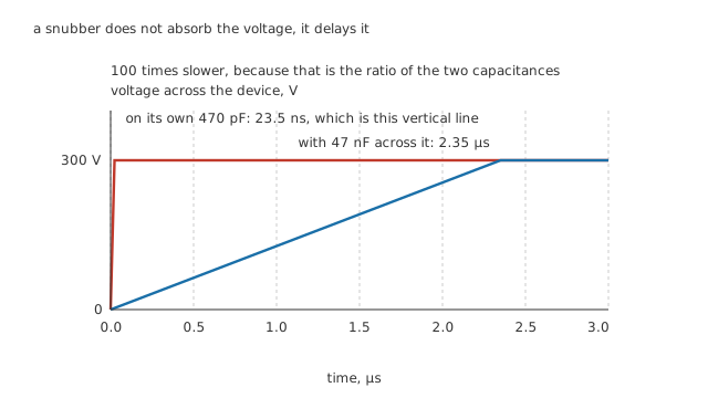
A snubber does not absorb the voltage. It delays it.
A snubber is a capacitor and a resistor in series, across the device. The capacitor is the working part and the resistor is what stops the cure becoming a new disease.
Worked example — The slope, and the ratio that sets it
The current has to charge whatever capacitance it finds. On the device's own 470 pF, reaching 300 V at 6.0 A takes 23.5 ns.
Put 47 nF across the device and the same rise takes 2.35 µs.
That is 100 times slower, and the factor is exactly the ratio of the two capacitances. The snubber is not doing anything subtle: it is providing a hundred times more capacitance for the same current to fill.
The resistor is there because a capacitor alone across a resonant loop does not damp it — it just moves the resonance somewhere lower and leaves it ringing. The resistor is what turns the oscillation into heat.
Worked example — Choosing the resistor
Critical damping for 22 µH against 47 nF wants 43.3 Ω.
Fitting the nearest standard value, 47 Ω, gives a damping ratio of 1.09.
Slightly over one is the right side to be on. Under-damping leaves the ring you were trying to remove; heavily over-damping makes the resistor so large that the capacitor cannot charge quickly enough to do its job, and the device sees the fast edge anyway.
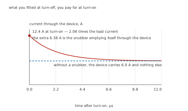
What you fit at turn-off, you pay for at turn-on.
Worked example — What the snubber costs
Every time the device turns off, the capacitor charges to 300 V and stores 2.12 mJ; every time it turns on, that energy comes back out through the resistor. At 100 Hz of switching, the resistor dissipates 423 mW.
Worse, the capacitor empties through the device. At turn-on it adds 6.38 A to the load's 6.0 A, taking the peak to 12.4 A — 2.06 times the current the device would otherwise carry, decaying with the snubber's own 2.21 µs.
So a snubber sized to protect the device at turn-off is a snubber that stresses it at turn-on, and the design is a compromise between the two rather than a solution to one.
Professional
A clamp is not a snubber
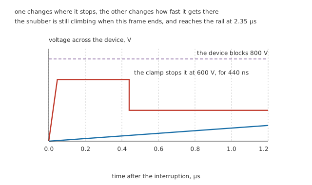
One changes where it stops. The other changes how fast it gets there.
A clamp — a transient voltage suppressor, a varistor, or a zener large enough for the job — does nothing at all until the voltage across it reaches its own threshold, and then conducts hard enough to hold it there.
Worked example — What the clamp has to swallow
The loop's 22 µH carrying 6.0 A holds 396 µJ, and all of it has to go into the clamp.
With the clamp holding 600 V against a 300 V rail, the current falls at a rate set by the difference, so the clamp conducts for 440 ns.
While it does, it is dissipating 3.60 kW. A part rated for a few watts continuously is expected to absorb kilowatts for a fraction of a microsecond, and the two ratings are not the same rating.
Now the distinction that matters. A snubber has no idea what voltage it is protecting against. It slows every transient by the same factor, which is fine if you know how large the transient is and bad if you do not. A clamp has no idea how fast the voltage is rising. It limits the peak and does nothing whatever about the rate of change, which is what triggers a thyristor into conduction without a gate signal.
Fit only a snubber and a large enough transient still exceeds the rating, more slowly. Fit only a clamp and the device is safe from over-voltage and still turns itself on from the rate of rise. This is why the circuit below carries both, and why most real power circuits do too.
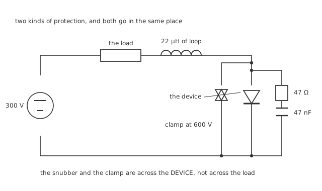
Two kinds of protection, and both go in the same place: across the device, not across the load.
Getting the connection right
Both go across the device, not across the load. This is the error that survives review most often, because across the load looks tidier and is wrong: it is the device's own voltage that has to be controlled, and putting the snubber across the load leaves the loop inductance between the snubber and the thing it is protecting.
Loop area matters as much as component value. A snubber with 50 mm of lead between it and the device has inductance of its own in series with it, and above a megahertz that inductance is what the transient sees rather than the capacitor.
The resistor is a pulse component, not an average one. It dissipates 423 mW on average and takes 2.12 mJ in a burst lasting microseconds. Wirewound parts have inductance and are the wrong choice; a small film part rated for its average power may still fail on the pulse.
A snubber capacitor lives a hard life. It sees the full rail, a fast edge, and a large current, every cycle, for years. This is one of the places a polypropylene film capacitor is specified rather than preferred.
Fusing does not protect a semiconductor. A fuse protects the wiring and the building from a device that has already failed short, which is how power semiconductors usually fail. Making the fuse blow deliberately, to save something downstream, is a different technique with its own lesson: the crowbar.
Common mistakes
- Reading a large transient as a fault — 1.52 kV on a 300 V rail is what a 22 µH loop and 470 pF of device capacitance do to a 6.0 A interruption. Nothing is broken; the circuit is behaving exactly as its own parasitics require.
- Fitting the snubber across the load — it has to be across the device, because it is the device's voltage that needs controlling, and the loop inductance sits between the two.
- Treating a snubber as a clamp — it slows the rise by 100 times and limits nothing. A transient large enough to exceed the rating still will, more slowly.
- Treating a clamp as a snubber — it stops the voltage at 600 V and does nothing at all to the rate of rise, which is what turns a thyristor on without a gate signal.
- Forgetting the turn-on cost — the snubber capacitor discharges through the device, adding 6.38 A to a 6.0 A load and taking the turn-on peak to 12.4 A.
- Ignoring layout — only 3.26 µH is enough to reach the 800 V rating, which is about 3.26 metres of wire. A tidy loop is the cheapest protection available and the only one that costs nothing.
Frequently asked questions
Why does the voltage ring instead of just spiking?
Because the loop has capacitance as well as inductance. A pure inductance interrupted into a resistance gives an exponential decay, which is the flyback case. Here the device's own 470 pF is across the switch, so the 22 µH and the 470 pF exchange energy back and forth at 1.57 MHz, and the voltage overshoots in both directions rather than decaying from one.
How do I choose the snubber capacitor?
By how slow you need the rise to be. The factor is simply the ratio of the snubber's capacitance to the device's own, so 47 nF against 470 pF gives exactly 100 times, taking the rise from 23.5 ns to 2.35 µs. Larger is slower and also more expensive at turn-on, because everything you put in has to come back out through the device.
Why does a snubber need a resistor at all?
Because a capacitor alone does not damp anything — it lowers the resonant frequency and leaves the circuit ringing at the new one. The resistor is where the energy goes. Critical damping here wants 43.3 Ω, and the nearest standard 47 Ω gives a damping ratio of 1.09, just on the safe side of one.
Can I use a TVS instead of a snubber?
Only if the problem is the peak rather than the rate. A clamp holding 600 V absorbs the loop's 396 µJ in 440 ns, at an instantaneous 3.60 kW, and does its job well. What it does not do is slow the rise, so a device that is vulnerable to fast edges — any thyristor — is still vulnerable with a clamp fitted and no snubber.
Does the wiring really matter that much?
Yes, and it is the largest single variable. The peak voltage grows as the square root of the loop inductance, and at a declared 1.0 µH per metre it takes only about 3.26 metres of loop to reach the 800 V rating. Shortening the loop is free, works on every transient at once, and cannot be got wrong.
Knowledge check
A device interrupting 6.0 A on a 300 V rail sits in a loop of 22 µH with 470 pF across it. What voltage does it see? (Show answer)
How much does a 47 nF snubber slow the voltage rise, and why exactly that much? (Show answer)
What does fitting that snubber cost? (Show answer)
A clamp is fitted instead. What does it have to absorb, and for how long? (Show answer)
How much loop inductance can this device tolerate before it exceeds its rating? (Show answer)
One email a month from the bench
New circuits, lessons, part guides and calculators, on the first Sunday of each month.