
Quick Answer
A transient voltage suppressor is a diode built to break down very fast, absorb a brief pulse of energy and survive it. It sits across the thing it protects, passes nothing below its stand-off voltage, and clamps above it. It is chosen on pulse energy, not on continuous power.
Safety
This lesson names no standard and publishes no standard-attached number. Every suppressor rating here is an illustration chosen to make the arithmetic work, and the surge waveform drawn is deliberately not one of the standard test pulses. Protection that has to meet a specification is designed against the actual text of the governing document and verified by test, not from a teaching page. The one exception is the human-body-model trio, which is restated from ESD basics and attributed there.
Intuition
The net on the hillside
Above a mountain road you sometimes see a wire net bolted across the slope. For years it does nothing whatsoever. Then one afternoon a boulder comes down and the net catches it, deforming to absorb the energy and keeping the road open. Afterwards, somebody inspects it.
Three things about that net are worth carrying into electronics. It is rated for a certain size of boulder, and a bigger one goes through. What matters is the energy the boulder arrives with, not how heavy it is or how fast it is on its own. And the net has to be up the slope from the road rather than lying across it, because a net in the road's way would be a hazard rather than a protection.
A transient voltage suppressor gives a circuit the same net. It goes across a circuit's supply or signal line, in parallel with what it protects. Below a chosen voltage it does nothing at all and the circuit does not know it is there. Above that voltage it conducts hard, holding the line down while whatever arrived is dumped into it.
The thing it is protecting against is not a steady overvoltage. It is a transient: a spike lasting microseconds, from a switch opening somewhere, a nearby motor, a cable being plugged in, or a person's finger. Those events carry small amounts of energy at very high voltage, which is a shape a semiconductor can survive and a shape that destroys anything not designed for it.
Practitioner
The five voltages
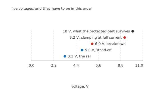
Five voltages, and they have to be in this order.
Choosing a suppressor is arranging five numbers in the right order, and every one of them has to be checked.
The rail is what normally sits there: 3.3 V here.
The stand-off voltage is the highest the part may see while doing nothing: 5.0 V, which leaves 1.7 V of margin.
The breakdown voltage is where it starts conducting properly, quoted at a small test current: 6.0 V at 1.0 mA.
The clamping voltage is what it actually holds the line to at full pulse current: 9.2 V at 10 A.
The protected part's absolute maximum has to be above that: 10 V, leaving 0.80 V.
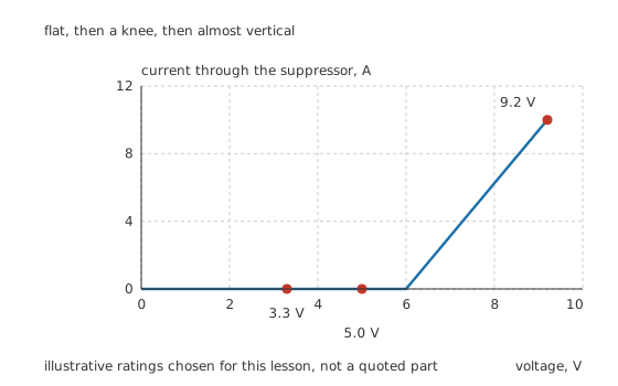
Flat, then a knee, then almost vertical.
Worked example — What it costs while it is doing nothing
At its 5.0 V stand-off the part leaks 1.0 µA, so it dissipates 5.0 µW continuously.
At the other extreme, clamping at 9.2 V with 10 A flowing, it is dissipating 92 W.
More than seven orders of magnitude apart, in the same component, and both are normal operation.
That range is the whole point of the part, and it is why the two numbers are specified so differently: one is a leakage and one is a peak, and neither is a continuous power rating.
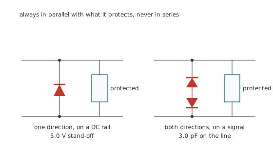
Always in parallel with what it protects, never in series.
On a DC rail one device is enough, with its cathode facing the positive rail so that it is reverse biased in normal use. On a signal that swings either way, two are used back to back so that neither polarity can simply forward-conduct.
Engineer
Energy, not voltage, is the rating
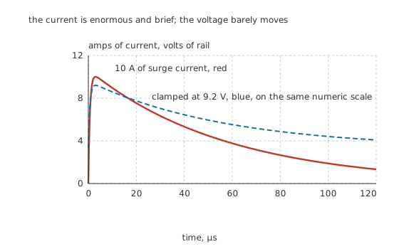
The current is enormous and brief; the voltage barely moves.
The number that decides whether a suppressor survives is not the voltage and not the current on its own. It is how much energy arrives and how long it takes to arrive.
Worked example — What the illustrative pulse actually delivers
The pulse above rises to 10 A in 2.0 µs and the part clamps at 9.2 V while it does.
Integrating the whole pulse gives 5.56 mJ deposited in the junction.
Compare that with an electrostatic discharge from a person. The human-body model charges 100 pF to 2 kV behind 1.5 kΩ, which is 1.33 A of peak current and 200 µJ of stored energy.
The surge carries 27.8 times the energy of that discharge, and it is the energy that decides which part is needed.
That comparison is the most useful thing in this lesson. A part that comfortably survives a finger may be nowhere near enough for a cable-borne surge, even though the finger arrives at a far higher voltage. Voltage decides whether something breaks down; energy decides whether the part that broke down survives it.
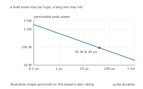
A brief pulse may be huge; a long one may not.
Suppressor ratings are always quoted against a pulse duration, and the shorter the pulse the larger the permissible power. The reason is thermal: what fails is the junction reaching its own temperature limit, and over a few microseconds the heat has not left the small volume where it was made, while over a millisecond it has spread into the whole die. The curve here is drawn as an inverse square root through this lesson's declared 92 W at 40 µs, to show the shape rather than to reproduce anything published.
The consequence for design is that comparing two parts means comparing them at the same pulse duration. A headline peak-power figure quoted against a short pulse and another quoted against a long one are not comparable numbers at all.
Professional
What it costs the circuit it protects
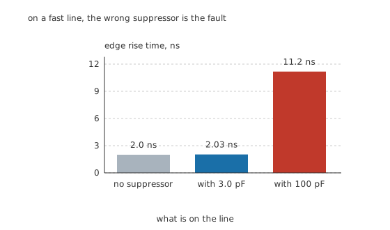
On a fast line, the wrong suppressor is the fault.
A suppressor is a large-area junction, and a large-area junction is a capacitor. On a power rail nobody notices. On a signal line it is often the dominant consideration.
Worked example — What the capacitance does to an edge
Take a 2.0 ns edge driven from 50 Ω.
A 3.0 pF suppressor gives a time constant of 150 ps, a rise time of its own of 330 ps, and a combined edge of 2.03 ns. That is 1.35 % slower, which nobody would notice.
A 100 pF suppressor gives 5.0 ns, 11 ns and a combined 11.2 ns, which is 459 % slower. The signal is gone.
Low-capacitance parts exist precisely for this, and they achieve it by putting a small suppressor behind an arrangement of ordinary fast diodes so that the large junction never appears across the line. The trade is a slightly higher clamping voltage.
Where a suppressor is the wrong part
On the mains, for lightning-scale energy. That is joules rather than millijoules, and it is a varistor's job or a gas discharge tube's. Suppressors are often used behind those as a second stage, catching what the first stage lets through.
As a voltage regulator. A Zener holds a rail continuously at milliwatts. A suppressor is a much larger junction with much looser voltage tolerance, designed for microseconds. Using one to regulate wastes its area and gets a poor reference.
In series with anything. A suppressor in series does nothing useful and everything harmful. This sounds too obvious to state, and it is a real fault found in the field.
Three things to check that people forget
The clamping voltage at the current you will actually see, not at the knee. The gap between 6.0 V and 9.2 V is where protection designs fail: a part that "clamps at six volts" is clamping at nine when it is working hardest, and if the protected part dies at eight the design is worthless.
The layout. A suppressor works through the inductance of its own connections, and a few nanohenries carrying amps per nanosecond develops volts. Short, wide traces to the connector's ground, and the suppressor physically before the protected part in the current's path rather than beside it, matter as much as the part choice.
Whether it failed. Suppressors normally fail short, which is a useful failure because the circuit obviously stops working rather than quietly losing its protection. But a part that has taken repeated pulses inside its rating degrades gradually, and there is no way to tell from outside. Anything that has taken a hit worth investigating is worth replacing.
Common mistakes
- Choosing on breakdown voltage rather than clamping voltage — the part here breaks down at 6.0 V and clamps at 9.2 V at full current, and it is the 9.2 V that has to be inside what the protected part survives.
- Setting the stand-off voltage too close to the rail — the part must pass nothing at the highest normal rail voltage, so 5.0 V against a 3.3 V rail is margin rather than waste.
- Comparing peak-power ratings quoted at different pulse durations — permissible power falls with duration, so two headline figures against different pulses are not comparable.
- Fitting a high-capacitance suppressor to a fast signal — 100 pF turns a 2.0 ns edge into 11.2 ns, which is 459 % slower and destroys the signal it was meant to protect.
- Ignoring the layout — the inductance of the suppressor's own connections develops real voltage at the current slew rates a transient brings, so a correctly chosen part badly connected does not work.
Frequently asked questions
What does a TVS diode do?
It sits across a supply or a signal line, does nothing below its stand-off voltage, and conducts hard above it. That clamps the line to a known voltage while the energy in a transient is dumped into the suppressor instead of into the circuit it protects.
What is the difference between a TVS diode and a Zener diode?
Purpose and construction. A Zener holds a rail continuously at milliwatts and is specified on voltage accuracy. A TVS has a much larger junction area, a looser voltage tolerance and a rating written in pulse energy against a stated pulse duration. Substituting a signal Zener for a TVS gives a part that clamps once.
How do I choose the voltage of a TVS?
Work through five numbers in order. The rail must sit below the stand-off voltage with margin; the breakdown voltage is above that; the clamping voltage at full rated pulse current must still be below what the protected part can survive. The clamping voltage, not the breakdown voltage, is the one that has to fit.
Why does the peak power rating depend on the pulse length?
Because what fails is the junction reaching its temperature limit. Over a few microseconds the heat is still confined to the small volume where it was made; over a millisecond it has spread through the whole die. So a short pulse may deposit far more power without reaching the limit, and ratings are meaningless without the duration they were measured against.
Will a TVS diode slow down my signal?
It can, badly. A suppressor is a large-area junction and therefore a capacitor. Three picofarads on a 2 ns edge from 50 Ω is unnoticeable; a hundred picofarads turns the same edge into eleven nanoseconds. Low-capacitance parts exist for signal lines and work by keeping the large junction off the line itself.