
A Zener diode is built to break down in reverse at a specified voltage and survive it. Above the knee it holds roughly that voltage while its current varies widely, which makes it a simple reference or clamp. It is a rough one: tolerance, slope impedance and temperature all move the number.
Intuition
The perforated line on a sheet of stamps
A sheet of stamps tears where the perforations are. That is not damage and it is not a defect in the paper; somebody put the holes there so the sheet would separate at a chosen place, repeatably, and would hold together everywhere else. Tearing a stamp off is the sheet working as designed.
An ordinary diode that is pushed too far backwards breaks down and usually destroys itself. A Zener diode is the same structure with the doping arranged so that breakdown happens at a chosen, low, well-defined voltage and does no harm at all, provided the current is limited. Reverse breakdown stops being a failure and becomes the operating mode.
What makes that useful is what the characteristic looks like once it has broken down. Below the breakdown voltage the part passes almost nothing. Above it, the current climbs almost vertically, which means large changes in current produce very small changes in voltage. Anything with that shape can be used to hold a voltage steady.
Two cautions, and both matter more than beginners expect. The current has to be limited by something else, because the Zener will not limit it: put one straight across a supply and it will conduct until something fails. And "holds a voltage steady" is a relative claim. It is steady enough for a rough reference and nowhere near steady enough for a precision one.
Practitioner
The characteristic, and how it is specified
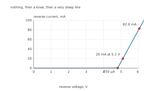
Nothing, then a knee, then a very steep line.
The part this lesson uses is 5.1 V at a test current of 20 mA, with a 5 % tolerance and a 500 mW rating. That is a complete specification, and every number below comes from it.
The voltage is quoted at one current, and only there. Above the knee the characteristic is not vertical: it leans, and the lean is the slope impedance, here 15 Ω. Extending that lean back to zero current gives an intercept of 4.80 V, which is the piecewise model every figure in this lesson is drawn from.
Below breakdown the part is simply a reverse-biased diode: at 3.0 V it passes about 5.0 µA and nothing interesting happens.
Worked example — How far the voltage moves when the current does
Change the current through the Zener by 10 mA and the voltage across it changes by 150 mV.
That is the whole of what "regulation" means for a bare Zener. It is a factor of about 17 better than the resistor it replaces — 255 Ω of operating-point resistance traded for a 15 Ω slope — and it is not remotely a fixed voltage.
Below 250 µA the part is on the knee, where the slope impedance climbs steeply and regulation collapses. Above 82.8 mA it exceeds its 500 mW rating.
Tolerance is on the nominal, and it is generous. A 5 % part nominally at 5.1 V may be anywhere from 4.85 V to 5.36 V at the test current, and every one of those is in specification.
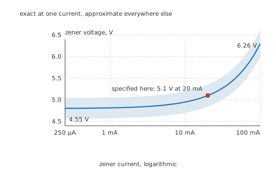
Exact at one current, approximate everywhere else.
Put the two together and the honest figure is uncomfortable. Across the usable current range, with tolerance, this part can be anything from 4.55 V to 6.26 V, a spread of 33.5 % of nominal. Designs that need better than that need something else.
Engineer
Two mechanisms wearing one name
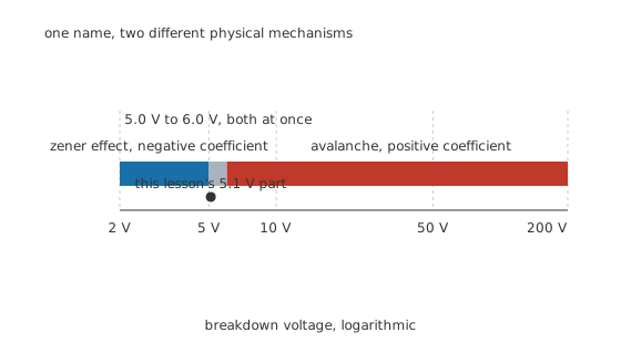
One name, two different physical mechanisms.
The name covers two unrelated pieces of physics, and knowing which one a part uses predicts how it behaves.
True Zener breakdown happens in heavily doped junctions with very narrow depletion regions. The field across that narrow region is enormous even at a few volts, and it pulls carriers straight out of their bonds. Warming the material loosens those bonds, so it takes slightly less voltage to do it, and the breakdown voltage falls with temperature.
Avalanche breakdown happens in more lightly doped junctions with wider depletion regions. A carrier is accelerated far enough to knock others loose, and those do the same, so one carrier becomes many. Warming the material makes collisions more frequent, so carriers travel less far between them and need more field to reach the required energy, and the breakdown voltage rises with temperature.
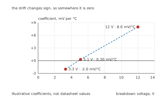
The drift changes sign, so somewhere it is zero.
Between roughly 5.0 V and 6.0 V both mechanisms act together and their opposite coefficients partly cancel, which is why the most stable simple references sit in that band and why so many designs use a part near five volts even when five volts is not the voltage they wanted.
Worked example — What temperature does to two different parts
Warm this 5.1 V part by 50 °C and its coefficient of 0.30 mV/°C moves it by 15 mV, which is inside the noise of everything else.
Do the same to a 12 V part at 8.0 mV/°C and it moves 400 mV, which is a serious error in most designs.
A 3.3 V part runs the other way at -2.0 mV/°C. The three coefficients here are illustrative figures chosen for this lesson rather than quoted from any datasheet; the sign change and roughly where it happens are the parts that generalise.
Where the power goes
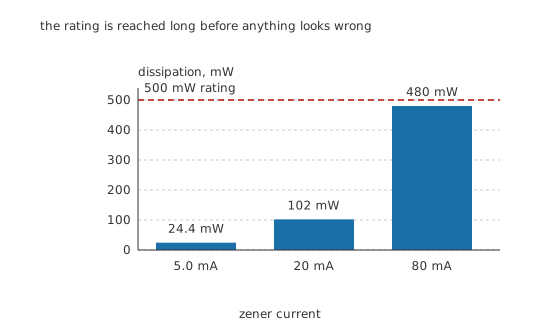
The rating is reached long before anything looks wrong.
Worked example — How close the rating really is
At its test current the part dissipates 102 mW, comfortable against 500 mW.
At 5.0 mA it dissipates only 24.4 mW, but it is also close to the knee and regulating poorly.
At 80 mA it reaches 480 mW, which is at the rating, and nothing about the part's behaviour warns you.
The dangerous case in a real circuit is the opposite of the intuitive one. In a shunt regulator the Zener carries whatever the load does not, so the worst dissipation happens at no load, when the whole of the available current goes through it. A design checked only at full load can fail the moment the load is disconnected.
Professional
Using one, and knowing when not to
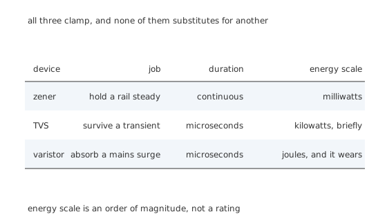
All three clamp, and none of them substitutes for another.
Always limit the current with something else. A resistor is the usual answer. The Zener sets the voltage; the resistor sets the current; neither does the other's job.
Bias it well above the knee. Below 250 µA the slope impedance rises sharply and the part stops regulating. A useful habit is to keep the Zener current at least a few times the load current it is stabilising, which also keeps the operating point away from the knee when the load takes its share.
Below about 5 V, expect worse. Low-voltage Zeners have a soft knee and a high slope impedance, so a 3.3 V part regulates noticeably worse than a 5.1 V one. Below about 2.4 V they effectively stop existing, and the answer is a forward-biased string of ordinary diodes or a proper reference.
Above about 5 V, expect drift. The coefficient grows with breakdown voltage, and a 12 V part in a warm enclosure moves by hundreds of millivolts.
Where it stops being the right part
As a precision reference. The tolerance, slope impedance and drift together put this part somewhere in a 33.5 % window. Integrated band-gap references do a hundred times better for similar money, and any design quoting a rail to better than a few percent should use one.
As surge protection. A Zener can clamp a transient, and small ones are used that way, but a TVS diode is the same idea built for it: much larger junction area, much higher peak power, and specified for pulse energy rather than continuous dissipation. Substituting a signal Zener for a TVS gives a part that clamps once.
Where the current is large. A shunt regulator wastes the difference between the source and the load as heat in the Zener, all the time. Above about a hundred milliwatts of waste, a series regulator is better on every count.
Two uses that are not regulation
Level shifting and clamping. A Zener in series with a signal shifts it by its breakdown voltage; a pair back to back clamps a signal symmetrically at a defined level, which is a common protection arrangement on an input pin.
As a noise source. Avalanche breakdown is a genuinely random process, and a reverse-biased junction in avalanche produces broadband noise that is usable as a hardware random source. It is also, in a regulator, an unwanted noise contribution that decoupling has to remove.
The larger lesson is that a Zener trades precision for simplicity, and that trade is a good one surprisingly often. Two components and a known error beat a precise circuit that nobody has room for.
Common mistakes
- Connecting a Zener directly across a supply — nothing limits the current, so it conducts until either it or the supply fails. A series resistor is not optional.
- Treating the marked voltage as the voltage you will get — a 5 % part at 5.1 V may be anywhere from 4.85 V to 5.36 V before the slope impedance is even considered.
- Checking the dissipation only at full load — in a shunt regulator the Zener carries the most current when the load takes the least, so no load is the worst case.
- Running the Zener near its knee — below about 250 µA the slope impedance climbs steeply and regulation stops working, however good the part is above it.
- Using a high-voltage Zener where drift matters — the temperature coefficient grows with breakdown voltage, and a 12 V part can move hundreds of millivolts over a 50 °C rise.
Parts used in this topic
Frequently asked questions
What is a Zener diode?
A diode built so that reverse breakdown happens at a specified low voltage and does no damage, as long as the current is limited by something else in the circuit. Above the breakdown knee it holds approximately that voltage while its current varies over a wide range, which is what makes it usable as a simple reference or clamp.
Which way round does a Zener diode go?
Reversed, compared with an ordinary rectifier diode. Its cathode, the banded end, goes to the more positive side of the circuit, so the part is reverse biased and operating in breakdown. Fitted the other way round it behaves as an ordinary silicon diode dropping about 0.7 V.
Why does the Zener voltage change with current?
Because the breakdown characteristic is very steep but not vertical, and its lean is the slope impedance. On the part here that is 15 Ω, so 10 mA more current means 150 mV more voltage. That number, together with the part's tolerance, sets how good a reference it can possibly be.
Why do Zener diodes near 5 V have almost no temperature drift?
Because two mechanisms overlap there. True Zener breakdown dominates below about 5 V and has a negative coefficient; avalanche breakdown dominates above about 6 V and has a positive one. In between both act and their opposite drifts largely cancel, which is why simple references cluster around five volts.
Can I use a Zener diode for surge protection?
For small transients on a signal line, yes, and it is done. For real surge energy, no. A TVS diode is the same principle built for the job, with a much larger junction, a much higher peak power rating and a specification written in pulse energy rather than continuous dissipation. A signal Zener in that position clamps once.
Knowledge check
A 5.1 V, 5 % Zener has a slope impedance of 15 Ω. How steady is its voltage really? (Show answer)
Why must a Zener always have a series resistor? (Show answer)
A 5.1 V Zener carries 80 mA. Is that acceptable on a 500 mW part? (Show answer)
Why do Zener diodes around 5 V drift so little with temperature? (Show answer)
In a shunt regulator, when does the Zener dissipate the most? (Show answer)
One email a month from the bench
New circuits, lessons, part guides and calculators, on the first Sunday of each month.