
A crowbar detects an overvoltage and deliberately shorts the supply rail, forcing the fuse upstream to clear. It uses a thyristor because a thyristor latches, so a brief fault produces a permanent short. It protects the load by destroying the fuse, and it only works if the fuse gives up first.
Intuition
Breaking it to save it
Protection usually means prevention. A fuse opens, a clamp limits, a regulator folds back — each of them tries to stop something bad happening and leaves the equipment intact if it succeeds.
A crowbar is not like that. When it decides something has gone wrong, it puts a dead short across the supply rail, on purpose, and holds it there. The supply goes into current limit or the fuse blows or the transformer buzzes and gives up, and none of that is an accident. The circuit is called a crowbar because the mental picture is throwing a crowbar across a pair of live rails, and the picture is accurate.
A fire sprinkler is the same bargain. Nobody wants a room full of water and ruined equipment. They want it a great deal more than they want a room full of fire, so the sprinkler is designed to cause damage as fast as possible once the alternative is worse. A crowbar destroys a fuse, possibly a supply, and definitely an afternoon, in order not to destroy something that costs more.
The thing it usually protects is a rail full of semiconductors. A regulator's pass element fails short and the raw supply — which might be three times the regulated rail — arrives on a bus feeding everything on the board. There is no time to think about it. The rail's own decoupling capacitance is the only thing slowing it down, and it is not slowing it down for long.
The reason a crowbar uses a thyristor is the same reason the previous lessons kept calling that a nuisance: once it turns on, it stays on. A fault that lasts microseconds produces a short that lasts until somebody replaces something, and that is exactly the behaviour you want from a device whose job is to refuse to let the equipment come back up.
Safety
A crowbar makes a large current on purpose, and everything a large current does is on the table. 200 A through the thyristor is 240 W for as long as it lasts. Traces vaporise, connectors weld, batteries vent and electrolytics fail loudly. Test one at a bench supply with its own current limit set low, never on the equipment it will eventually protect.
A crowbar without a fuse is a short circuit with a delay. If nothing upstream can clear, the thyristor conducts until something else fails, and what fails next is whatever has the least margin — a transformer winding, a track, a connector pin. The fuse is not an optional companion to a crowbar; it is half the circuit.
Never work on a rail that has crowbarred and assume it is dead. The rail is at the thyristor's on-state drop, not at zero, and the raw supply behind the fuse is still live. What has changed is which conductor is dangerous, not whether one is.
Every number in this lesson is an invented illustration, and the safety-relevant ones especially: the 45 A²s fuse melting integral, the 150 A²s device withstand, the 7.0 V absolute maximum, the 5.6 V zener and the 2.0 µs response time. Melting integrals and absolute maximum ratings are standard-attached and part-specific, and choosing real ones is the design job this lesson describes rather than performs.
Practitioner
The circuit, and what it costs the load not to have it
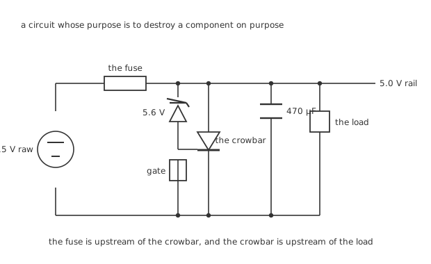
The fuse is upstream of the crowbar, and the crowbar is upstream of the load.
Four parts, and the order of them is the circuit. A zener senses the rail. Its current feeds the thyristor's gate through a resistor. The thyristor sits across the rail. The fuse sits between the raw supply and all of it.
Worked example — The trip point, and the room around it
The gate sees the rail minus the zener's 5.6 V, and needs 0.70 V of its own. So the crowbar fires at 6.3 V.
Against a 5.0 V rail that is 1.3 V of headroom, or 26 % — enough that ordinary tolerance, ripple and load steps will not fire it by accident.
Against the load's 7.0 V absolute maximum it leaves 0.70 V to work in. That number is smaller than it looks, and layer three is about why.
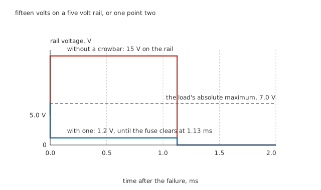
Fifteen volts on a five volt rail, or one point two.
Worked example — What happens when the pass element shorts
The raw 15 V reaches the rail through the supply's 50 mΩ and the thyristor's own 25 mΩ, so once the crowbar fires the fault current is 200 A.
The fuse's melting integral is 45 A²s, and at that current it is reached in 1.13 ms.
While that happens the load — 3.0 Ω of it — sits at 1.2 V instead of 15 V, which is 480 mW instead of 75 W.
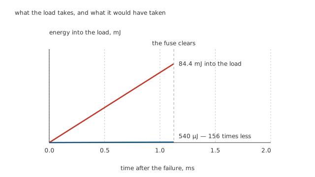
Both lines are straight, because both powers are constant. The difference is a factor, not an offset.
Worked example — What the load is spared
Over the 1.13 ms the fuse takes, an unprotected load absorbs 84.4 mJ.
A protected one absorbs 540 µJ.
That is 156 times less energy, and it is the whole argument. The thyristor takes 270 mJ doing it, which is why a crowbar thyristor is a surge-rated part rather than a general-purpose one.
Engineer
The fuse has to give up first
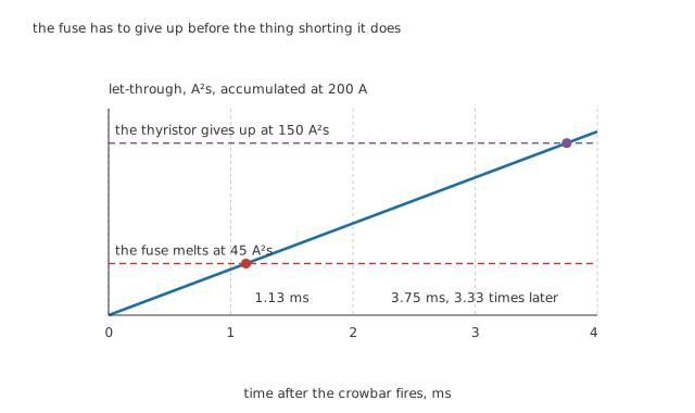
A crowbar that outlives its fuse has saved the load. One that does not has simply moved the failure.
Both the fuse and the thyristor have a limit on how much let-through they can take before they give up, and both limits are expressed the same way, as a current squared multiplied by a time. The design requirement is nothing more than an ordering: the fuse's number has to be reached first, by a margin that no combination of tolerances can reverse.
Worked example — Coordination
At 200 A, the fuse's 45 A²s is reached at 1.13 ms.
The thyristor's 150 A²s is not reached until 3.75 ms.
The ratio is 3.33, and that is the coordination margin. It has to survive a fuse at the slow end of its tolerance, a thyristor at the weak end of its own, a hot day and a supply whose impedance is lower than assumed — because a lower supply impedance means more current, which reaches both limits sooner but does not change their ratio.
The direction of that last point is worth being clear about. Because both limits are I²t, raising the fault current shortens both times by the same factor and leaves the coordination ratio untouched. What breaks coordination is not a larger fault; it is a fuse chosen for its current rating without regard to its melting integral, or a thyristor chosen for its steady-state current without regard to its surge rating.
The response time is the real limit
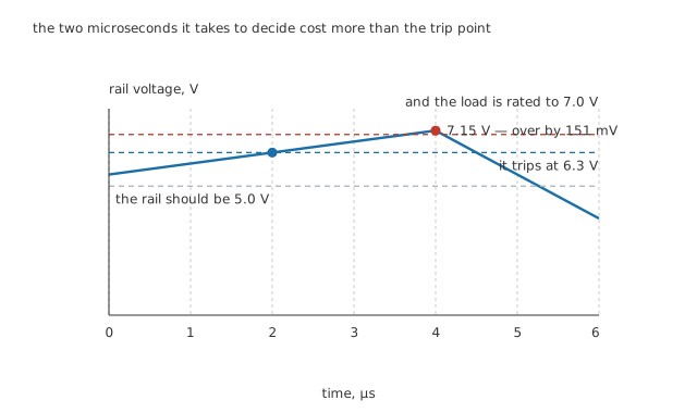
The two microseconds it takes to decide cost more than the trip point does.
Everything so far has treated the crowbar as instantaneous. It is not, and the delay is where the design actually fails.
Worked example — What the delay costs
While the zener conducts and the gate charges — a declared 2.0 µs — the fault current is still flowing into the rail's 470 µF of decoupling.
A constant current into a capacitance is a constant slope, so the rail rises a further 851 mV.
Starting from the 6.3 V trip point, that puts the peak at 7.15 V — which is 151 mV above the load's 7.0 V absolute maximum.
The circuit as drawn does not work. It fires correctly, at the right voltage, and the load has already been over its rating by the time it does.
That result is not a contrived one. It is what happens when a designer picks a trip point with comfortable headroom above the rail, checks it against the absolute maximum, and never multiplies the response time by the fault current.
Professional
Making it actually work
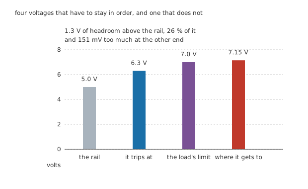
Four voltages that have to stay in order, and one that does not.
Worked example — The trip point that would have worked
Work backwards. The peak has to stay under 7.0 V, and the response time will always add 851 mV to whatever the trip point is.
So the trip point has to be at most 6.15 V.
Against the 5.0 V rail that still leaves headroom, but far less of it, and the design has become a squeeze between two constraints rather than a choice with room in it.
There are three ways out of that squeeze, and they are worth knowing in order.
Make it faster. The overshoot is proportional to the response time, so halving the delay halves the problem. A comparator with a reference is faster than a zener feeding a gate, costs a few more components, and turns a marginal design into a comfortable one.
Make the rail's capacitance work for you. The overshoot is inversely proportional to the decoupling capacitance, so more of it buys time. This is the only place in electronics where large bulk capacitance on a rail is a protection feature rather than an inrush problem, and it is worth remembering because the instinct usually runs the other way.
Reduce the fault current. It sets the slope. A supply whose own limiting works, or a series element that cannot deliver hundreds of amps, makes every other number easier — though it also lengthens the fuse's clearing time, so the coordination has to be rechecked rather than assumed.
Where crowbars still belong
A crowbar is a last resort and should be designed as one. It should never operate in normal service, and if it does, something else is already wrong. A circuit that trips occasionally has a trip point too close to its rail, and nuisance tripping on a crowbar is not an inconvenience — it is an outage plus a service visit.
Modern regulators often include the function. Overvoltage protection built into a supply's controller sees the fault earlier, at the source, and can shut the pass element down instead of shorting its output. Where that is available it is better in every respect.
Electronic fuses do the job without the destruction. A current-limiting switch with an overvoltage input disconnects rather than shorting, resets rather than needing replacement, and costs one component. For low-voltage rails this has largely replaced the discrete crowbar.
What keeps the crowbar alive is speed and certainty. It responds in microseconds, it has no firmware, it does not need a supply of its own to work, and it latches — so once it has decided, nothing can talk it out of the decision. In equipment where an overvoltage means an expensive load or a hazard rather than an inconvenience, that combination is still hard to beat.
The failure that catches everyone: a crowbar fitted downstream of nothing. If the supply has no fuse and no current limit, the crowbar does not protect the load; it simply chooses which part of the equipment burns. Fit the fuse first, then check the coordination, and only then worry about the trip point.
Common mistakes
- Fitting a crowbar with no fuse upstream — the thyristor latches and conducts until something clears. With nothing designed to clear, whatever has the least margin fails instead, and that is not a protection scheme.
- Choosing the trip point without the response time — a 6.3 V trip on a rail rising at 200 A into 470 µF peaks at 7.15 V, which is 151 mV past a 7.0 V rating. The trip point is correct and the circuit still fails.
- Coordinating on current rating instead of let-through — the fuse must reach its 45 A²s before the thyristor reaches its 150 A²s, a margin of 3.33. Raising the fault current shortens both times equally and does not change that ratio; picking parts by their steady-state ratings does.
- Setting the trip point too close to the rail — 1.3 V of headroom is 26 %, and much less than that means ripple and load steps will fire it. A crowbar that nuisance-trips is an outage, not an inconvenience.
- Assuming a crowbarred rail is safe to touch — it sits at the thyristor's 1.2 V on-state drop, and the raw supply behind the fuse is still live.
- Testing one on the equipment it protects — 200 A through the thyristor is 240 W while it lasts. Test at a current-limited bench supply.
Frequently asked questions
Why use a thyristor rather than a transistor?
Because it latches. A transistor conducts only while it is driven, so a brief overvoltage would produce a brief short and the fault would come straight back. A thyristor turned on by a microsecond-long event stays on until its current is removed, which means the equipment cannot come back up until somebody has looked at it. That is the desired behaviour, not a side effect.
What actually makes the fuse blow?
The crowbar. With the pass element shorted, the raw 15 V reaches the rail through 50 mΩ of supply impedance and the thyristor's 25 mΩ, which is 200 A. The fuse's melting integral of 45 A²s is reached in 1.13 ms. Without the crowbar the load's own current might never be enough to clear the fuse at all, which is the whole reason the circuit exists.
How much does the crowbar actually save?
A factor of 156 in energy into the load. Unprotected, it sits at 15 V across 3.0 Ω, taking 84.4 mJ before the fuse clears; protected, it sits at the thyristor's 1.2 V drop and takes 540 µJ. The thyristor absorbs 270 mJ doing it, which is why it has to be a surge-rated part.
Why does the response time matter more than the trip point?
Because the rail keeps rising while the crowbar decides. 200 A into 470 µF for 2.0 µs is 851 mV, added to whatever the trip point was. A trip point of 6.3 V therefore peaks at 7.15 V, 151 mV past a 7.0 V rating — so the trip point can be chosen perfectly and the design still fail. The trip point that would have worked here is 6.15 V.
Are crowbars still used?
Less than they were on low-voltage rails, where a regulator's built-in overvoltage protection or an electronic fuse does the job without destroying anything. What keeps them alive is that a crowbar responds in microseconds, needs no supply of its own, has no firmware to fail, and latches. Where the load is expensive or the overvoltage is a hazard, that combination is still worth a blown fuse.
Knowledge check
A 5.6 V zener gates a thyristor across a 5.0 V rail. Where does it trip, and is that sensible? (Show answer)
A pass element shorts, putting 15 V on the rail through 50 mΩ. What does the crowbar do, and how long does it take? (Show answer)
How much energy does the crowbar save the load, and what does it absorb itself? (Show answer)
Why must the fuse's let-through limit be reached before the thyristor's? (Show answer)
The trip point is 6.3 V and the load is rated to 7.0 V. Why does the circuit still fail? (Show answer)
One email a month from the bench
New circuits, lessons, part guides and calculators, on the first Sunday of each month.