
A thyristor, or silicon controlled rectifier, blocks voltage in both directions until a small current into its gate turns it on. After that it conducts one way and holds itself on, ignoring the gate entirely. The only way to turn it off is to starve it of current.
Intuition
The switch you cannot un-press
Most switching devices are obedient. Hold a transistor's base or gate where you want it and it stays where you put it; let go and it goes back. The control terminal is in charge for as long as the circuit runs, which is why a transistor needs its drive maintained and why losing the drive is a safe failure.
A thyristor is not like that. Give its gate a brief nudge and it turns on, and then it stops listening. You can disconnect the gate, short it, tie it to the cathode, walk away — the device goes on conducting. It has latched, and the only thing that will release it is taking away the current it is carrying.
That sounds like a defect, and for most jobs it is. It is also the reason the part exists.
A mousetrap is the nearest everyday thing. A trap takes a feather-light touch to set off and then does something violent, and the touch has no further say in what happens; the energy was already stored, and the trigger only decided when. A thyristor works the same way, with the important difference that nobody has to reset it by hand. It resets itself the moment the current through it falls far enough — which, on an alternating supply, happens a hundred times a second for free.
That is the whole design. A tiny, brief signal commands a large, sustained current, at a device cost of one silicon component and no continuous drive power at all. On mains, where the current politely returns to zero twice a cycle, the awkward part of the bargain costs nothing. That is why light dimmers, motor speed controls, soft starters and heater controllers were built from thyristors long before anything else was cheap enough, and why they still are.
Safety
The thyristors worth using are mains parts, and mains work is not bench work. Everything downstream of this lesson — phase control, solid-state relays, crowbars — puts a thyristor in a circuit where the whole device sits at line potential, and a device that has latched cannot be turned off by removing its drive. Unplugging is the off switch. There is no other one. Read electrical safety before building anything that plugs into a wall, and treat mains construction as work for someone qualified under your local wiring code.
Every number in this lesson is an explicitly invented illustration, and that includes all of them. The blocking voltage of 400 V, the breakover at 440 V, the gate trigger current of 5.0 mA, the 40 mA latching and 15 mA holding currents, the on-state threshold of 0.90 V with its 50 mΩ of slope, the 30 pF of junction capacitance and the 1.8 °C/W thermal resistance are all chosen to make the arithmetic legible. They belong to no part. A real device's are on its datasheet, they vary widely across the family, and the safety-relevant ones — voltage rating, surge current, the rate of rise the device tolerates — are exactly the ones you must never take from a lesson.
Practitioner
Two transistors that will not let go of each other
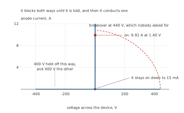
Two blocking regions, one conducting branch, and the conducting branch is almost invisible at the scale the blocking demands.
Start with the characteristic, because it is not the shape a diode or a transistor draws. There are two blocking regions, forward and reverse. There is one conducting branch. And there is no smooth road between them: the device is either off or on, and the transition happens in nanoseconds rather than being something you can sit in the middle of.
The scale of that picture is worth a moment. The on-state region is 1.40 V wide on an axis that has to reach 500 V in each direction to show the blocking — 0.14 % of the width of the figure. Everything interesting about conducting is invisible at the scale that makes blocking visible, and that tension runs through the whole component.
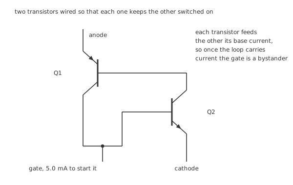
Four nodes, two devices, and a loop that feeds itself once it has started.
Inside, the structure is four alternating layers of doped silicon, which is three PN junctions in a row. The useful way to think about it is the model in the second figure: split the four layers down the middle and you have a PNP and an NPN sharing their middle two layers, wired so that each transistor's collector current is the other's base current.
That wiring is the whole behaviour. With no gate current, neither transistor has base current, so neither has collector current, so neither gets base current. The loop sits at zero and the device blocks. Push a little current into the gate and the NPN starts conducting, which supplies the PNP's base, which supplies the NPN's base, which supplies more of the PNP's — and the loop takes over. Once the two current gains multiply out to one or more, the pair holds itself in conduction with nothing from outside.
Worked example — What the device settles at once it is on
Put the device in series with 4.7 Ω across 48 V. Once it is on, its own drop is 0.90 V plus 50 mΩ multiplied by whatever current flows, so the current and the drop have to agree with each other.
Solving the two together gives 9.92 A, and at that current the device's drop is 1.40 V.
The gate that started all this needed 5.0 mA. The device is carrying 1983 times that, and no longer needs any of it.
Engineer
Three small currents, and none of them is the load's
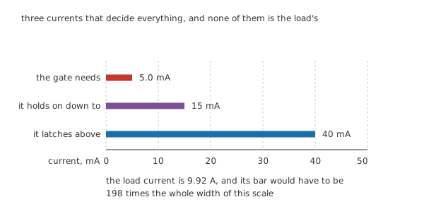
One scale through zero, so the lengths are the currents. The load's current does not fit and is not squeezed in.
A thyristor circuit works or fails on three thresholds, and every one of them is small enough to overlook on a schematic.
The gate trigger current starts the process: 5.0 mA at about 0.80 V, costing 4.0 mW for as long as you hold it. Hold it for 20 µs and turning the device on has cost you 80 nJ in total.
The latching current — 40 mA here — is what the main terminals must reach before the internal loop can sustain itself. Below it, removing the gate drops the device straight back out, which is why a circuit that triggers reliably into a heavy load can refuse to trigger into a light one. That failure looks like a faulty gate drive and is not one.
The holding current works the other way round. An already-conducting device gives up when its main current falls below 15 mA, which is 2.67 times smaller than the current it needed to latch. Getting in is harder than staying in, for the same reason it is in a relay: the conditions that sustain a state are not the conditions that establish it.
Against the load current of 9.92 A, the holding current is 0.15 %. That is why the figure does not draw the load current: its bar would need to be 198 times the whole width of the scale.
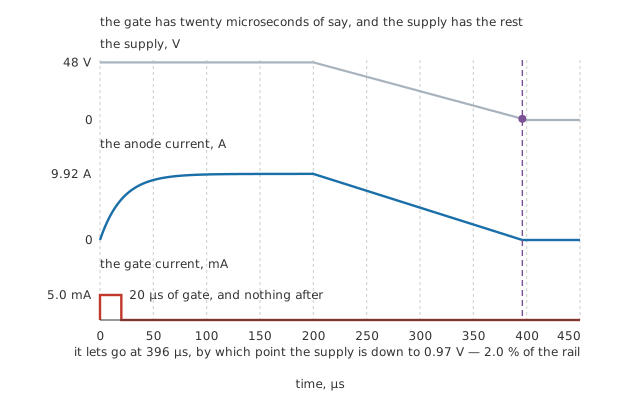
The gate has twenty microseconds of say in this, and the supply has the rest.
Worked example — How long the gate actually has to hold on
The circuit's stray inductance of 100 µH against the loop's resistance gives a time constant of 21 µs, so the current does not appear instantly — it rises exponentially.
It passes the 40 mA latching threshold at 85 ns. After that the gate is redundant.
A 20 µs gate pulse is therefore 235 times longer than the job needs, which is exactly the margin you want: the latching current has to be reached under the worst load the circuit will ever see, not the best.
Now the other end. The gate is gone, the current is flowing, and the supply starts falling. The device does not care. It goes on conducting all the way down until the current finally drops below 15 mA, and that happens when the supply has fallen to 0.97 V — 2.0 % of where it started, at 396 µs.
The supply has to fall to within a volt of zero before the device lets go. Everything else about using thyristors follows from that one sentence. On alternating current it is free and automatic; on a steady DC rail it is a serious engineering problem.
Professional
Getting it off again, and what it costs while it is on
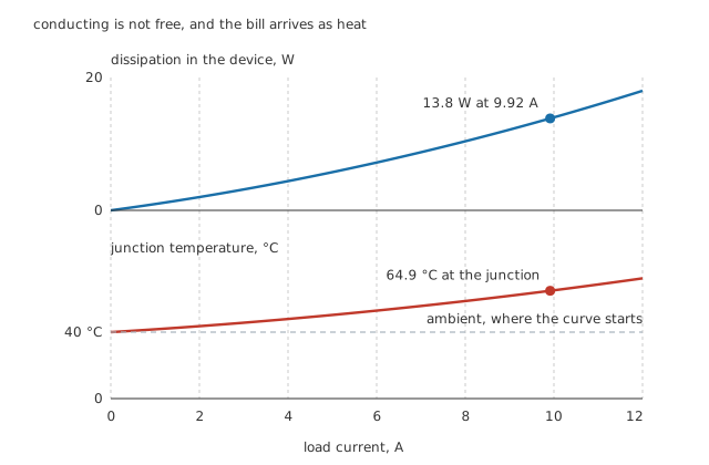
Neither is a straight line, because the on-state drop grows with the current it is dropping.
Worked example — The heat a conducting thyristor makes
At 9.92 A the device drops 1.40 V, so it dissipates 13.8 W.
Through a declared 1.8 °C/W from a 40 °C ambient, that puts the junction at 64.9 °C.
A volt and a bit sounds like nothing until it is multiplied by ten amps. This is the number that decides whether the part needs a heatsink, and on anything carrying real current it does.
Turning it off
On AC, you get turn-off for nothing. The current passes through zero at the end of every half cycle, falls below the holding current on its way, and the device switches itself off without being asked. Then it blocks until the next gate pulse. That mechanism is called natural commutation, it is the reason thyristors and mains grew up together, and it is the whole basis of phase control.
On DC there is no such kindness, and you have to arrange the interruption yourself.
Worked example — What it takes to force it off on DC
The device needs its current held at zero — in practice held slightly negative — for its turn-off time of 40 µs before it will block again.
At 9.92 A, that is 397 µC of charge that something else has to carry.
Held off the 48 V rail, that charge needs 8.3 µF, plus a second switch to connect it, plus a way of charging it back up for next time.
The circuit around the thyristor is now larger than the thyristor, and this is why nobody chooses one for a DC switching job any more.
The gate you did not connect
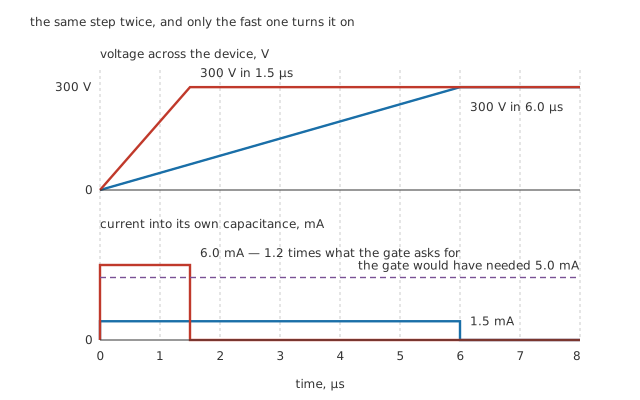
Only the fast edge crosses the trigger threshold, and it does it with nothing connected to the gate at all.
A thyristor has capacitance across its blocking junction, and a capacitance with a changing voltage across it passes current. If that current arrives where the gate current would have arrived, the device cannot tell the difference.
Worked example — Turned on by a voltage step alone
Take 300 V arriving across the device over 6.0 µs. Through 30 pF that is 1.5 mA, comfortably under the 5.0 mA the gate would need.
Deliver the same step in 1.5 µs instead and it becomes 6.0 mA, which is 1.2 times the trigger current.
Nothing was connected to the gate. The device turned itself on because the voltage across it changed quickly, and a nearby motor starting, a contactor closing or a lightning surge on the incoming line all change voltages quickly.
This is the parameter datasheets call critical rate of rise of off-state voltage, and it is why snubbers exist. Breaking over from too much voltage, in the figure at the top of layer two, is the same failure arriving by a different road: both are the device turning on when nothing asked it to.
Relatives worth knowing about
A triac is the version that conducts both ways, which is what an AC load actually wants, and it is the next lesson.
A unijunction transistor is not a thyristor but grew up beside one, as the cheapest way to make the gate pulse a thyristor needs; the glossary entry covers it.
Gate turn-off thyristors do exist, and a large enough negative gate current will switch one off. They are specialist parts, the negative pulse is far larger than the positive one that turned the device on, and they have been squeezed hard by IGBTs in the applications that used to need them.
For anything you can turn off with a gate, use something you can turn off with a gate. A thyristor earns its place where the current is going to zero anyway, where the surge rating matters more than the control, or where the latching is the point — which is exactly what a crowbar is.
Common mistakes
- Expecting the gate to turn it off — it will not, at any current, in any polarity that an ordinary thyristor accepts. Once the main current is above the 40 mA latching threshold the gate is a bystander, and the device only stops when its current falls below 15 mA.
- Triggering reliably on the bench and intermittently in the field — a light load may never reach the latching current, so the device drops out the instant the gate pulse ends. Test at the lightest load the circuit will ever see, not the heaviest.
- Sizing the gate pulse by the trigger current alone — 20 µs against the 85 ns the latch actually took looks wasteful, and it is the margin that makes the circuit work into a load that is slower to build current.
- Forgetting the on-state drop is not constant — 1.40 V at 9.92 A is 13.8 W, and the junction reaches 64.9 °C above a 40 °C ambient through a modest thermal resistance. Both grow faster than the current does.
- Treating a fast voltage edge as harmless — the same 300 V arriving in 1.5 µs instead of 6.0 µs drives 6.0 mA through the device's own capacitance, more than the 5.0 mA the gate needs, and turns it on with nothing connected to the gate.
- Choosing a thyristor for a DC switching job — turning it off means forcing its current to zero for the whole turn-off time, which here needs 8.3 µF, another switch and a way to recharge it.
Frequently asked questions
Why can a thyristor's gate not turn it off?
Because the gate is wired to one transistor's base in a two-transistor loop, and once that loop is running each transistor is supplied by the other, not by the gate. Pulling current out of the gate steals from a supply that is no longer the limiting one. Gate turn-off thyristors change the internal geometry so a large negative pulse can win, but an ordinary one cannot be persuaded.
What is the difference between latching current and holding current?
Latching current is what the main terminals must reach before the gate can be released — 40 mA in this lesson. Holding current is what an already-conducting device falls below before it gives up — 15 mA, which is 2.67 times smaller. Getting in is harder than staying in, and a circuit that fails only on light loads is usually failing the first threshold, not the second.
Why are thyristors so often found on mains and so rarely on DC?
Because alternating current turns them off for free. The current passes through zero at the end of every half cycle and falls below the holding current on the way, so the device blocks again with no help. On DC nothing takes the current away, and the circuitry to force it to zero is bigger and more expensive than the thyristor it is switching off.
Can a thyristor turn on without a gate signal?
Yes, in two ways, and both are failures rather than features. Too much voltage across it and it breaks over — at 440 V for the device in this lesson. Too fast a voltage rise and its own junction capacitance passes enough current to look like a gate signal: 300 V in 1.5 µs gives 6.0 mA against a 5.0 mA trigger threshold. Snubbers exist to slow the second one down.
How much does it cost to turn one on?
Almost nothing. The gate takes 5.0 mA at 0.80 V, which is 4.0 mW, and only for the length of the pulse — 80 nJ for a 20 µs one. That is the appeal: a signal too small to measure casually commands a load current 1983 times larger, and then stops costing anything at all.
Knowledge check
A thyristor drops 0.90 V plus 50 mΩ of slope resistance and sits in series with 4.7 Ω across a 48 V supply. What flows, and what does the device dissipate? (Show answer)
What are the three small currents that decide whether a thyristor circuit works? (Show answer)
A 20 µs gate pulse triggers a circuit whose stray inductance gives a 21 µs time constant. Is the pulse long enough, and by how much? (Show answer)
Why does turning a thyristor off on a DC supply need so much hardware? (Show answer)
How can a thyristor turn on when its gate is disconnected? (Show answer)
One email a month from the bench
New circuits, lessons, part guides and calculators, on the first Sunday of each month.