
Quick Answer
A triac conducts in either direction once triggered, which suits alternating current, and turns itself off at every zero crossing. A diac has no gate at all: it blocks until the voltage across it reaches its breakover point, then collapses to a lower voltage and delivers a sharp pulse, in either polarity.
Intuition
A switch with no favourite side
Alternating current spends half its time going the other way. A thyristor does not, so putting one in an AC circuit throws half the supply away and leaves the load a lumpy half-wave version of what it should have had.
The obvious repair is two thyristors, wired the opposite way round from each other, so that whichever way the current is trying to go there is a device pointing that way. It works. It also needs two gate drives, and the two gates sit at different potentials, which is a genuinely awkward thing to arrange on a circuit at mains voltage.
A triac is that pair built as one device, with one gate that works for both halves. Push current into it and the device conducts whichever way the load current wants to go, and it stops at the end of the half cycle like any thyristor does.
Think of a revolving door. You can push it from either side, it carries whoever is in it until the compartment closes, and then it stops on its own and waits to be pushed again. Nobody has to reverse it between one person and the next; the door is symmetrical and does not care which way you came from. A triac has that symmetry too, and the stopping-and-waiting is not a limitation but the mechanism.
The diac is the smaller companion. It has two terminals, no gate, and one trick: it refuses to conduct until the voltage across it reaches a certain level, at which point it gives way suddenly and hands over everything that was waiting behind it. That sudden handover is what a triac's gate likes best, and the two parts are usually found together.
Safety
A triac in a mains circuit has no isolation anywhere in it. The gate is referred to one of the main terminals, which means the gate, the trigger circuit, the diac and anything else connected to them sit at line potential the entire time the equipment is plugged in. That is the important difference from a relay, where the coil and the contacts share nothing. Anything low-voltage-looking on the trigger side of a triac is not low voltage. It is mains with a small signal on it.
Do not put an oscilloscope ground clip anywhere in such a circuit. The clip is bonded to the earth of the building through the instrument, so connecting it to a point at line potential makes a short circuit through the earth system, and the fault current does not pass through anything designed to limit it.
Every number in this lesson is an invented illustration. The triac's 1.2 V threshold with its 60 mΩ slope, the 10 mA gate current, the 25 mA holding current, the diac's 32 V breakover and 8.0 V snapback, and the 3.5 °C/W thermal resistance belong to no part. 230 V and 50 Hz appear as nominal class values, which is naming rather than specification; no wiring-code figure, no creepage or clearance distance and no approval rating is published here, because those are standard-attached and this lesson has not verified any of them. Building mains equipment is work for somebody qualified under the local code, and electrical safety comes first.
Practitioner
The same device, facing both ways
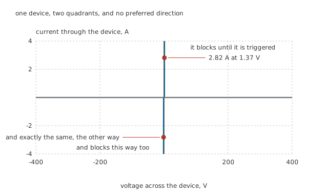
Two branches, mirrored through the origin, and nothing in the picture prefers a direction.
Draw the characteristic and the difference from a thyristor is immediate. There is a conducting branch in the first quadrant and another in the third, and they are the same branch reflected. The device blocks in both directions until it is triggered, and once triggered it conducts in whichever direction the circuit is pushing.
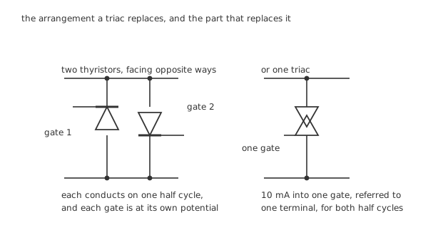
The arrangement on the left works. The one on the right works with one gate drive instead of two, at one potential instead of two.
Inside, a triac is not literally two thyristors, though the model is close enough to reason with. It is one five-layer structure that can be triggered into conduction in either polarity, with a gate referred to one of the two main terminals. Those terminals are called MT1 and MT2 rather than anode and cathode, because neither is permanently one or the other.
Worked example — What the load actually gets
Put 115 Ω across a nominal 230 V line, whose peak is 325 V.
Solving that peak against the device's own drop gives a peak current of 2.82 A, at which the device is dropping 1.37 V.
An uncut sine has an RMS value of 1.99 A, so the load takes 456 W.
Compare that with the same load on a single thyristor, which would conduct on one half cycle only and deliver half of it.
The gate that arranges all of this needs 10 mA at about 1.0 V, and only for as long as it takes the main current to establish itself.
There is a wrinkle worth naming now, because it bites later. The polarity of the gate current and the polarity of the main current can each be positive or negative, giving four combinations, and a triac is not equally happy in all of them. Most parts are noticeably less sensitive in one of the four, and many modern parts do not support it at all — which is why datasheets talk about three-quadrant and four-quadrant devices, and why a trigger circuit that works one way round may fail the other.
Engineer
The part with no gate, and what it hands over
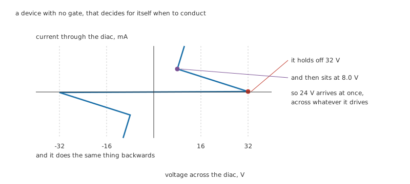
The segment running left and up is negative resistance, and it is the whole reason the part exists.
A diac blocks in both directions until the voltage across it reaches 32 V. Then it does something a resistor cannot: as current starts to flow, the voltage across it falls, settling near 8.0 V. The region between those two is a negative resistance, and whatever charge was sitting behind the diac is delivered in one go.
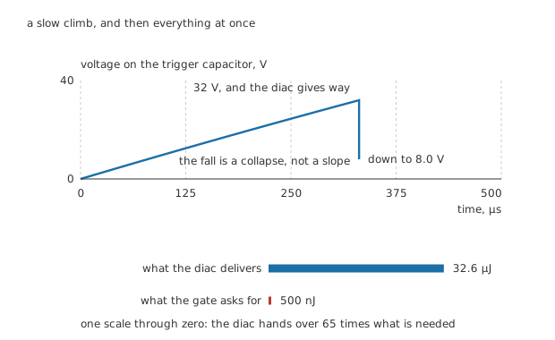
A slow climb, and then everything at once. The two bars share one scale through zero.
Worked example — How big the diac's pulse is
A 68 nF capacitor charged to the diac's 32 V breakover holds 34.8 µJ.
When the diac gives way the capacitor falls to 8.0 V, where it still holds 2.2 µJ. The difference, 32.6 µJ, goes into the gate.
Charging through 47 kΩ, the capacitor reaches breakover at 331 µs, and everything above happens in the instant after that.
The gate wanted 10 mW for 50 µs, which is 500 nJ.
So the diac delivers 65 times what is needed, and delivers it in one step rather than as a slow ramp. That margin is the point: a gate fed by a slowly rising voltage triggers at an unpredictable moment, and a gate hit with 24 V all at once does not.
The reason this matters more than it looks is that a triac has to be re-triggered constantly.
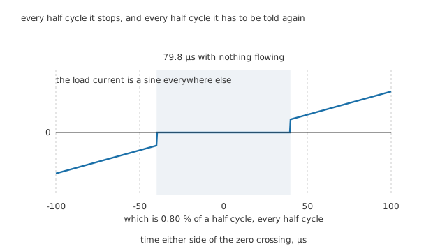
Every half cycle it stops, and every half cycle it has to be told again.
Worked example — The gap the device cannot bridge
For the triac to carry even its 25 mA holding current, the supply has to be above its own drop plus what that current costs in the loop: 4.08 V.
On a 325 V peak, the line is below that for 39.9 µs either side of each zero crossing, so the device is off for 79.8 µs altogether.
Against a half cycle of 10 ms, that is 0.80 %.
It is a small fraction and it is not optional. A hundred times a second the device stops conducting, and a hundred times a second something has to trigger it again — which is why a triac circuit contains a trigger circuit, not just a switch.
Professional
What it costs, and the load that breaks it
Worked example — The heat a conducting triac makes
A triac's drop has two parts and they bill different currents. The 1.2 V threshold is a fixed voltage, so it costs the average current: 1.79 A gives 2.15 W.
The 60 mΩ slope is a resistance, so it costs the RMS current squared: 238 mW.
Together that is 2.39 W, and through a declared 3.5 °C/W from a 35 °C ambient the junction sits at 43.4 °C.
Using one current for both terms is the classic way to get this wrong, and it errs in the unsafe direction.
That heat is the real price of having no moving parts. A relay contact of 40 mΩ carrying the same 1.99 A makes 159 mW, so the triac produces 15.1 times as much heat doing the same job. A relay also leaks nothing when open and drops nothing when closed. What it cannot do is switch a hundred times a second for twenty years without wearing out.
The load that breaks it
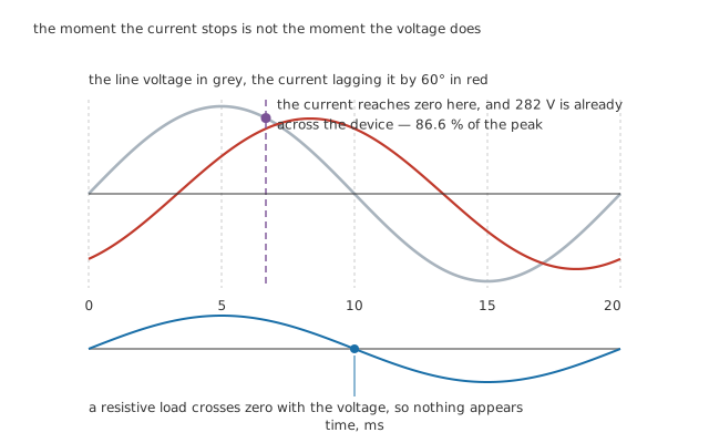
The moment the current stops is not the moment the voltage does.
Everything above assumed a resistive load, where current and voltage cross zero together. Motors, transformers and solenoids do not oblige.
Worked example — Why an inductive load is the hard case
With the current lagging the line by 60°, the current reaches zero while the line is still well up its own curve.
At that instant the line is at 282 V, which is 86.6 % of the peak.
The triac has just stopped conducting, and that voltage appears across it immediately. With a resistive load the same instant carries nothing at all, because the two cross zero together.
A voltage arriving that fast across a device that has only just stopped conducting is enough to turn it straight back on, exactly as the fast edge did in the previous lesson. The device never blocks, the load never switches off, and the failure looks like a shorted triac even though the part is undamaged. Datasheets specify this separately from the ordinary rate-of-rise figure and call it commutating dV/dt, because the device is at its most vulnerable in the microseconds after conducting. Snubbers exist mostly for this.
Choosing and using one
Start with the RMS current and the heat it makes, not the peak. 2.39 W inside a plastic package needs somewhere to go, and the package alone rarely provides it above a couple of amps.
Check the load's character before the load's size. A triac comfortable with a heater of a given rating may fail within minutes on a motor of half that rating, and the reason is commutation rather than current.
A triac has no off state you can trust for safety. It leaks when blocking, it can be turned on by a transient, and it will not disconnect anything. Isolation for maintenance is a mechanical switch or a plug, and nothing else.
Where the current is large, back-to-back thyristors come back. They cost two gate drives and two isolated supplies, and in return each device gets a whole half cycle to recover instead of being asked to block immediately after conducting.
Where the load is inductive and the control is anything but simple, use a solid-state relay. It packages the triac, the isolation and the trigger together, and takes the commutation problem on itself.
Everything so far has treated the trigger as arriving at some unspecified moment. Choosing when in the half cycle it arrives is what turns a switch into a control, and that is phase control.
Common mistakes
- Treating the trigger circuit as low voltage — the gate is referred to a main terminal, so everything attached to it sits at line potential. There is no isolation anywhere in a bare triac circuit.
- Assuming one gate polarity works everywhere — gate and main current each have two polarities, and most triacs are weak or unusable in one of the four combinations. A trigger circuit proven on one half cycle is not proven.
- Costing the conduction loss with a single current — the 1.2 V threshold bills the 1.79 A average and the 60 mΩ slope bills the 1.99 A RMS squared. Adding those gives 2.39 W; using either current for both terms understates it.
- Forgetting the device switches off at every crossing — the supply is below 4.08 V for 79.8 µs around each one, 0.80 % of a half cycle, and the triac has to be triggered again afterwards. A circuit that fires once per cycle instead of once per half cycle delivers half the power and looks broken in a confusing way.
- Fitting a triac sized by current to an inductive load — with the current lagging by 60° the line is already at 282 V when conduction stops, 86.6 % of the peak, and that step can turn the device straight back on.
- Expecting a triac to isolate anything — it leaks when off, and a transient can turn it on. Use a mechanical disconnect before working on the load.
Frequently asked questions
Why not just use two thyristors instead of a triac?
Sometimes you should, and at high currents it is the usual answer. The cost is two gate drives whose reference terminals sit at different potentials, which needs two isolated supplies or a pulse transformer each. The benefit is that each device gets a full half cycle to recover before it has to block again, which is exactly what a triac does not get and exactly why triacs struggle with inductive loads.
What does a diac add that a resistor divider could not?
Suddenness. A divider brings the gate voltage up gradually, so the exact moment of triggering depends on the gate's own threshold, which drifts with temperature and varies between parts. A diac holds everything back to 32 V and then collapses to 8.0 V, handing the gate 32.6 µJ in one step against the 500 nJ it needs. The trigger point becomes a property of the diac rather than of the triac's gate.
Why does a triac need re-triggering every half cycle?
Because it turns itself off every half cycle. Around each zero crossing the supply is below the 4.08 V needed to push even the 25 mA holding current through the loop, so the device drops out for 79.8 µs, which is 0.80 % of the half cycle. Whatever triggered it the first time has to do so again after the crossing, a hundred times a second on a 50 Hz supply.
Why do triacs fail on motors when they are fine on heaters?
Because a motor's current lags its voltage. On a resistive load the current and the voltage reach zero together, so the device stops conducting at a moment when there is nothing to block. With the current lagging by 60° the line is already at 282 V when the current reaches zero, and that voltage lands on a device that has had no time to recover. It turns back on, and the load never switches off.
Is a triac quieter or more efficient than a relay?
Quieter and longer-lived, but not more efficient. Carrying 1.99 A this triac dissipates 2.39 W against 159 mW in a 40 mΩ relay contact, which is 15.1 times as much heat, and it needs somewhere to put it. The triac wins on switching speed, on switching rate and on having nothing to wear out; the relay wins on losses, on leakage and on actually disconnecting the load.