
Phase control delivers less power by conducting for only part of each half cycle. The supply is untouched; only the moment the device is triggered moves. Because the sine carries most of its energy near its peak, power and firing angle are related by a curve rather than a straight line.
Intuition
You cannot turn mains down
The supply that arrives at a socket is not adjustable. It is a sine of a fixed size at a fixed frequency, and nothing you connect to it changes that. So if a lamp is to run at half power, something has to take away half the energy, and there are only two ways to do it: throw the surplus away as heat, or refuse to accept it in the first place.
Throwing it away works and is what a series resistor does. It also means the controller dissipates a large fraction of what the load does, which for anything above a few watts is an unpleasant object to have in a wall box.
Refusing to accept it is what phase control does. A triac starts each half cycle switched off, and the circuit waits a chosen fraction of that half cycle before triggering it. Whatever is left of the sine after that moment reaches the load; whatever came before it does not. Nothing is converted to heat, because nothing was taken.
The awkward part is that you get no say in when the conducting stops. The device switches itself off at the zero crossing, as any thyristor does, and the next half cycle starts from off again. All you control is the start.
A serving hatch with a fixed closing time works the same way. However late you join the queue, the hatch shuts when it shuts, and arriving later means getting less. Arriving halfway through does not get you half, though, because the queue is not evenly spread across the opening — and neither is a sine. That mismatch is what the rest of this lesson is about.
Safety
A dimmer is a mains circuit with no isolation anywhere in it, and it is the most dangerous thing in this department. The triac's gate is referred to one of its own main terminals, so the resistor, the capacitor, the diac and the shaft of the control the user turns are all at line potential whenever the circuit is plugged in. There is no low-voltage side. A plastic knob and a plastic faceplate are the only things between a person and the supply, and they are doing that job on purpose.
An oscilloscope ground clip anywhere in this circuit is a short through the earth system. The clip is bonded to the building's earth through the instrument's own mains lead. Connect it to a point at line potential and the fault current flows through the probe lead, the instrument and the earth conductor, none of which is designed to carry it. Measuring a circuit like this needs a differential probe or an isolated instrument, and knowing which is part of the qualification.
Building one is work for somebody qualified under the local wiring code, and this lesson is not that qualification. 230 V and 50 Hz appear here as nominal class values, which is naming and not specification. No wiring-code figure, no creepage or clearance distance, no enclosure requirement and no approval rating is published anywhere in this lesson, because none of them has been verified first-hand and the standard for that is to publish none.
Every device number here is an invented illustration: the 1.3 V conducting drop, the 30 mA holding current, the 2.0 µs turn-on time, the 4.7 kΩ to 220 kΩ control and the 47 nF beside it. They belong to no part.
Practitioner
The supply never changes, only the moment you start
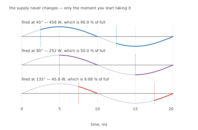
The grey trace is identical in all three. Only the start of the colour moves.
The firing angle is measured in degrees from the zero crossing, because that is where each half cycle begins. Fire at 45° and the device conducts for the remaining three-quarters of the half cycle; fire at 135° and it conducts for the last quarter.
Worked example — The angle, as something a circuit can actually wait for
A full cycle at 50 Hz is 20 ms, so a half cycle is 10 ms.
An angle of 45° is therefore a delay of 2.5 ms after the crossing, 90° is 5.0 ms, and 135° is 7.5 ms.
Those are the numbers the trigger circuit has to produce, twice per cycle, a hundred times a second, without drifting.
Now the arithmetic that decides what the load receives. The conducting part of the wave is a slice of a sine, so its RMS value is not a simple fraction of the whole. The integral gives a closed form in terms of the conduction angle — how much of the half cycle the device is on for — and it is worth writing down because everything else follows from it.
Worked example — What each setting actually delivers
The line's peak is 325 V, and with the device conducting for the whole half cycle the load sees the full 230 V and takes 504 W from 105 Ω.
Firing at 45° leaves an RMS of 219 V, which is 458 W, or 90.9 % of full power.
Firing at 90° gives 163 V and 252 W — 50.0 %, exactly.
Firing at 135° gives 69.3 V and 45.8 W, or 9.08 %.
Look at the first and last of those. Delaying by 45° costs less than a tenth of the power. Delaying by 135° leaves less than a tenth. The two add to 100 %, and that is not an accident of the angles chosen: it falls out of the integral for any pair of angles either side of the middle.
Engineer
Turning the knob is not turning the power
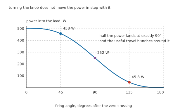
Half the power lands at exactly 90°, and the useful travel bunches around it.
Draw the whole sweep and the shape is an S. The first fifth of the travel does almost nothing, the last fifth does almost nothing, and everything happens in the middle. The reason is in the sine: a half cycle carries most of its energy near its peak, and the peak is in the middle.
That has a consequence anyone who has used a cheap dimmer will recognise. Most of the rotation does nothing much, then a small movement near the centre takes the lamp from bright to dim, and near the end it goes out abruptly. The control feels badly made. It is not — the physics is that shape, and a well-made dimmer spends real effort compensating for it in the trigger circuit.
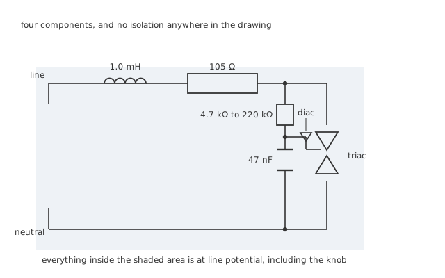
Four components and no isolation anywhere in the drawing, including the knob.
The trigger is the oldest circuit in the subject and is still what most dimmers contain: a resistor charges a capacitor from the line, and when the capacitor reaches the diac's breakover voltage it dumps into the gate. Turning the control changes the resistor, which changes how long the charging takes, which moves the firing angle.
Worked example — Why that resistor has to be so large
At the fast end, 4.7 kΩ with 47 nF gives 221 µs, which is 2.21 % of a half cycle. The capacitor is at the diac's threshold almost immediately, so the device fires early and the load runs nearly at full power.
At the slow end, 220 kΩ gives 10.3 ms — 1.03 times the half cycle itself.
That is the point of the large value: to delay firing into the last part of the half cycle, the time constant has to be comparable with the half cycle, and at mains frequency that means hundreds of kilohms against tens of nanofarads.
There is a wrinkle in that circuit which explains a lot of bad dimmer behaviour. The capacitor does not start each half cycle at zero, because the diac only discharges it down to its own snapback voltage. The starting point therefore depends on what happened last half cycle, and the circuit can settle into a state where alternate half cycles fire at different angles. That is called hysteresis or snap-on, the brightness then repeats once per full cycle instead of once per half cycle, so the flicker lands at the mains frequency rather than at twice it, and the cure is a second resistor and capacitor that most real dimmers have and most textbook schematics leave out.
Professional
What it costs, and what it costs everyone else
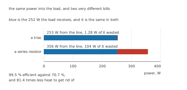
The same power into the load, and two very different bills.
Worked example — A dimmer against the resistor it replaced
At the half-power setting the load takes 252 W. The triac carries an average of 986 mA while it conducts, and at 1.3 V that costs 1.28 W.
A series resistor delivering the same 252 W to the same load would have to be 43.5 Ω, dropping 67.4 V at 1.55 A, which is 104 W.
So the line supplies 253 W in one case and 356 W in the other: 99.5 % efficient against 70.7 %.
The controller's own heat differs by 81.4 times, and that is the whole argument for the technique.
Somebody else pays for this
Nothing is free. The energy the dimmer does not take is energy it declined abruptly, and an abrupt decline is a fast edge on a wire that runs through the whole building.
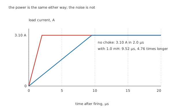
The power delivered is identical. The noise is not.
Worked example — What the choke is for
Fired at 90°, the voltage across the device the instant before it turns on is 325 V, and the instant after it is a volt or so. Without anything to slow it, the load current reaches 3.10 A in the device's own 2.0 µs.
Put 1.0 mH in series and the inductor holds the rate down: the same current now takes 9.52 µs.
That is 4.76 times longer. The load receives exactly the same power either way, because the choke's impedance at 50 Hz is negligible; what changes is the edge, and the interference falls with it.
A chopped sine is also a poor citizen electrically. Its current is not proportional to its voltage, so it draws harmonics the supply never asked for, and an ordinary averaging multimeter cannot measure it at all — which the lesson on RMS values covers in detail. On a small lamp none of this matters much. On a building full of them it is why the technique has been steadily regulated out of large installations.
The floor at the dim end
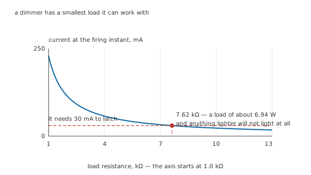
A dimmer has a smallest load it can work with, and it is not a small number.
Worked example — Why a dimmer stops working with a small lamp
At the dimmest setting the device is fired when the line is at 230 V. For it to latch, the load has to pull at least the 30 mA holding current at that instant.
That puts a ceiling on the load's resistance of 7.62 kΩ, which on this supply is a load of about 6.94 W.
Anything lighter cannot supply enough current at the moment of firing. The device never latches, and the load does not merely dim — it does nothing at all.
This is why a dimmer that ran a filament lamp for twenty years fails the week it is replaced with a small LED one. The new lamp draws a fraction of the current, its input is a rectifier and a capacitor rather than a resistance, and both of those break the assumption the trigger circuit was built on.
What replaced it
Trailing-edge dimming turns the device off part way through the half cycle instead of on, which needs a switch that can be turned off — so a MOSFET or an IGBT rather than a triac. The edge lands where the sine is small rather than large, so the interference is far lower, and capacitive loads behave much better.
Zero-cross switching gives up on partial cycles entirely and passes whole ones, switching only at the crossings where there is nothing to switch. It makes no fast edges at all, and it is what a solid-state relay does.
Everything above assumed the load is resistive. With a motor the current lags, so it reaches zero when the line is well up its own curve, and the device may not block at all — the failure covered in the previous lesson, and the reason snubbers exist.
Common mistakes
- Expecting the knob to track the brightness — the power against angle curve is an S. Firing at 45° still delivers 90.9 % of full power and firing at 135° delivers 9.08 %, so almost all of the useful control is in the middle third of the travel.
- Treating the trigger circuit as low voltage — the resistor, the capacitor, the diac and the control shaft are all at line potential. Nothing in a dimmer is isolated from the supply.
- Putting a scope ground clip on it — the clip is earthed through the instrument, so it makes a short circuit through the earth system, and nothing in that path is rated to carry the fault.
- Treating this lesson as a build guide — building one is work for somebody qualified under the local wiring code, and nothing here substitutes for that qualification.
- Omitting the choke because it does not change the power — it does not, and that is the point: it costs nothing in delivered power and it is the difference between an edge of 2.0 µs and one of 9.52 µs.
- Fitting a dimmer to a load smaller than it can latch — below about 6.94 W here, the load cannot supply the 30 mA holding current at the moment of firing, and it will not light at all rather than lighting dimly.
- Assuming a multimeter reading means anything — the output is a chopped sine, and an averaging meter's calibration constant was derived for a clean one.
Frequently asked questions
Why does a dimmer waste so much less than a resistor?
Because it never takes the energy in the first place. At the half-power setting the triac drops about a volt while conducting, which costs 1.28 W. A series resistor doing the same job would have to drop 67.4 V at 1.55 A, which is 104 W — 81.4 times as much, and all of it has to leave the wall box as heat.
Why is most of a dimmer's travel useless?
Because a sine carries most of its energy near its peak, which falls in the middle of the half cycle. Delaying the start by 45° removes only the first, smallest part of the wave and still leaves 90.9 % of the power; delaying by 135° leaves only the last, smallest part, 9.08 %. The two add to exactly the full-conduction power, and everything in between is compressed into the middle of the knob.
What is the choke for, if it does not change the power?
The edge. When the triac fires, the load current goes from nothing to 3.10 A in the device's own 2.0 µs, and an edge that fast on a wire that runs through the building radiates. With 1.0 mH in series the same current takes 9.52 µs, 4.76 times longer, while the delivered power is unchanged because the choke's impedance at 50 Hz is negligible.
Why did my dimmer stop working when I fitted LED lamps?
Two reasons at once. The new lamp draws far less current, and at the dim end the load has to pull the triac's 30 mA holding current at the moment of firing — which here needs a load of about 6.94 W or more. Below that the device never latches. On top of that, an LED lamp's input is a rectifier and a capacitor rather than a resistance, so it does not behave like the load the trigger circuit assumes.
Why does a dimmer sometimes flicker or snap on rather than fading up?
Because the trigger capacitor does not start each half cycle at zero. The diac only discharges it down to its own snapback voltage, so where it starts depends on what happened last half cycle, and the circuit can settle into firing alternate half cycles at different angles. Real dimmers add a second resistor and capacitor to break that feedback; simplified schematics usually leave it out.
Knowledge check
A triac fires at 90° into a 105 Ω load on a nominal 230 V line. What does the load receive, and how does that compare with full conduction? (Show answer)
Why is a dimmer's control so uneven, and what does the unevenness look like in numbers? (Show answer)
What would a series resistor cost to deliver the same power as the triac at its half-power setting? (Show answer)
A dimmer has a 1.0 mH choke in series with the load. What does it do? (Show answer)
Why does a dimmer have a minimum load? (Show answer)
One email a month from the bench
New circuits, lessons, part guides and calculators, on the first Sunday of each month.