
Quick Answer
An enhancement MOSFET conducts nothing until its gate passes a threshold, above which the field creates an inversion layer joining source to drain. Drain current then follows the square of the overdrive, and the device acts as a resistance below its knee and a current source above it.
Intuition
Nothing crosses until the tide reaches the causeway
A tidal causeway is either passable or it is not. Below a certain water level the road is clear and traffic crosses freely; above it, nothing does. There is no gradual version — the level either covers the road or it does not, and what happens either side of that point is a different situation rather than more or less of the same one.
An enhancement MOSFET has that shape, with the gate voltage in the place of the tide. Below the threshold there is no conducting channel at all, because the silicon under the oxide is the wrong type to carry current. Above it, the gate's field has pulled enough of the right carriers to the surface to invert a thin layer, and that layer joins the source to the drain.
The channel is created rather than narrowed, and that is the difference from a JFET, whose channel exists until something squeezes it. It is also why the two families work at opposite gate polarities and cannot substitute for one another.
Once the channel exists, two things follow. More gate voltage means more carriers pulled in, so the channel gets more conductive — and because both the carrier density and the field driving them rise together, the current follows the square of how far past threshold you have gone, not a straight line and not an exponential.
And what the channel does depends on how much voltage the drain is asking of it. Push only a little across and the channel behaves as an honest resistance. Push more and the channel pinches off at the drain end, after which the current stops rising and the device behaves as a current source instead.
Practitioner
The threshold, and the law above it
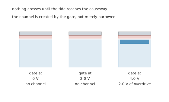
The channel is created by the gate, not merely narrowed.
Worked example — What the square law gives
This device has a threshold of 2.0 V and a conduction parameter of 50 mA per volt squared.
At 4.0 V the overdrive is 2.0 V and the drain passes 200 mA.
At 6.0 V the overdrive is 4.0 V — twice as much — and the drain passes 800 mA, which is 4.0 times as much. Doubling the overdrive quadruples the current, which is what "square law" means in practice.
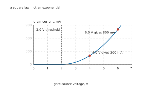
A square law, not an exponential.
The shape of that curve is worth comparing with a bipolar device's. A bipolar transistor's current is exponential in its base voltage, so its slope is steep everywhere and steepest where the current is largest. A MOSFET's is a parabola starting from zero, so it is flat near the threshold and steepens as it rises — which is exactly why MOSFET stages have little gain at small currents.
Worked example — The transconductance the square law gives up
The slope of the parabola at the operating point is 200 mS.
A bipolar device at the same 200 mA would offer 7.74 S.
That is a factor of 38.7, and it is the same trade a JFET makes for the same reason: a square law is a gentler curve than an exponential.
Engineer
The two regions, and the boundary between them
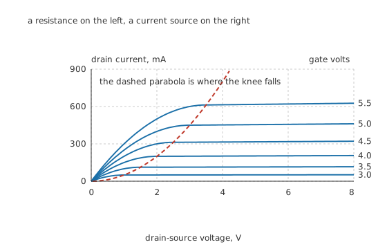
A resistance on the left, a current source on the right.
Every curve in that family does the same two things, and the dashed parabola marks where it changes.
Worked example — Where the knee falls, and why
Below the knee the whole channel is inverted along its length and the device is a resistance. As the drain voltage rises, the channel thins at the drain end, because the voltage between the gate and the channel there is the gate voltage minus whatever the drain has taken.
When the drain voltage reaches the overdrive, that difference has fallen to the threshold and the channel pinches off at the drain end. The knee therefore sits at the overdrive: 2.0 V for a gate at 4.0 V, and 4.0 V for a gate at 6.0 V.
Beyond that point, extra drain voltage falls across the pinched-off region rather than the channel, so the current barely changes. The device has become a current source.
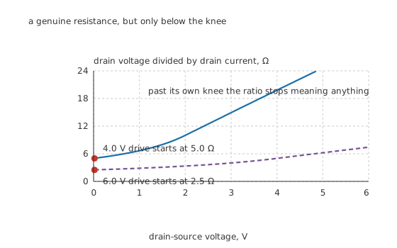
A genuine resistance, but only below the knee.
Worked example — The resistance below the knee, and the slope above it
Near the origin the device really is a resistance, and its value is set by the overdrive. At 4.0 V it is 5.0 Ω; at 6.0 V it is 2.5 Ω. Doubling the overdrive halves the resistance — a straight inverse, not a square.
Above the knee the current is not quite constant. The pinched-off region grows slightly with drain voltage, which shortens the channel and lifts the current a little.
At 200 mA the parameter 5.0 m per volt puts the output resistance at 1.0 kΩ, equivalent to an Early voltage of 200 V.
Those two facts are the two ways the device gets used. Deep in the triode region it is a switch or a controlled resistor; above the knee it is an amplifier or a current source. No practical circuit wants it to sit near the knee, where it is neither.
Professional
Two temperature effects, and one model that stops working
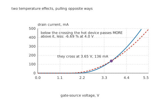
Two temperature effects, pulling opposite ways.
Worked example — Where the two effects cancel
Heat does two things and they disagree. The threshold falls, at about -4.0 mV per degree, taking the 25 °C value of 2.0 V down to 1.60 V at 125 °C. On its own that raises the current.
Carrier mobility also falls, roughly as a power of 1.5 in absolute temperature, taking the conduction parameter from 50 mA down to 32.4 mA. On its own that lowers it.
The two cancel at exactly one place: 3.65 V of gate drive, at 136 mA.
Below the crossing the threshold wins. At 3.0 V, where the cold device passes 50 mA, the hot one passes 27.0 % more. Above the crossing, mobility wins: at 4.0 V the hot device passes -6.69 %.
That crossing is not a curiosity, it is a safety boundary. A MOSFET operated as a switch runs far above it, where the current has a negative temperature coefficient — the hotter device takes less, so paralleled parts share and nothing runs away. A MOSFET operated in its linear region at low current, as an audio output stage or a hot-swap controller does, may sit below it, where the coefficient is positive and a local hot spot pulls more current, gets hotter, and pulls more still. That is thermal runaway in a device most people believe is immune to it.
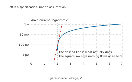
Off is a specification, not an assumption.
Three places the square law stops describing the device
Below threshold the current is not zero. The square law says nothing flows, and something does: an exponentially falling leakage that is still measurable a volt below threshold. For a switch that is the off-state specification; for dense logic it is the leakage that dominates idle power; for an analogue designer it is a usable region in its own right, where the device behaves much more like a bipolar transistor.
At high overdrive the square law flattens into a straight line. Carriers cannot exceed their saturation velocity, so past a certain field the current grows in proportion to the overdrive rather than its square. Short-channel devices reach that point early, which is why modern process transistors are poorly described by the model this lesson uses.
The parameters are not constants. The threshold varies between devices, drifts with temperature, and moves with the source-to-body voltage. Any circuit whose behaviour depends on the exact threshold is a circuit that will vary from board to board.
What this sets up
The device itself is where the on-resistance and the body diode live. Using one as a switch is the triode region put to work, and gate drive is what it costs to move between the two regions quickly. The knee and the pinch-off explanation here also transfer directly to the IGBT, which uses exactly this structure to control something else.
Common mistakes
- Expecting a gradual turn-on below threshold — the square law says nothing conducts below 2.0 V, and although a small exponential leakage really does flow, the device is not usefully controllable there.
- Confusing enhancement with depletion — this device needs its gate driven past 2.0 V to conduct at all, while a depletion device conducts with no drive. They work at opposite gate polarities.
- Assuming the on-resistance follows the square law too — current follows the square of the overdrive, but the resistance below the knee follows its inverse: 5.0 Ω at 2.0 V of overdrive and 2.5 Ω at 4.0 V.
- Treating a MOSFET as immune to thermal runaway — above the 3.65 V zero-coefficient point the current falls with temperature and it is immune. Below that point it rises, and a linear stage biased there can run away.
- Expecting bipolar transconductance — at 200 mA this device offers 200 mS against a bipolar device's 7.74 S, a factor of 38.7.
Frequently asked questions
What is actually happening at the threshold?
The gate's field has pulled enough minority carriers to the surface to invert a thin layer of the body, turning it into the same type as the source and drain and joining them. Below that point there is no continuous path of the right type at all, which is why the device is genuinely off rather than merely high-resistance.
Why does doubling the gate overdrive quadruple the current?
Because two things increase together. More overdrive pulls more carriers into the channel and also raises the field pushing them along it, and the product of the two is a square. Here 2.0 V of overdrive gives 200 mA and 4.0 V gives 800 mA.
Where does a MOSFET stop being a resistance?
At its knee, which sits where the drain voltage equals the gate overdrive — 2.0 V for a 4.0 V gate on this device. Below that the channel is inverted along its whole length and behaves ohmically; above it the channel has pinched off at the drain end and the device behaves as a current source.
Does a MOSFET's current rise or fall as it heats up?
Both, depending where it is biased. The threshold falls at about -4.0 mV per degree, raising current, while mobility falls, lowering it. The two cancel at 3.65 V of gate drive and 136 mA on this device. Below that a hot device passes 27.0 % more at 3.0 V; above it the shift is -6.69 % at 4.0 V.
Is the square law accurate?
For a discrete power or small-signal device in saturation, well enough to design with. It fails in three places: below threshold, where it predicts zero and the real device leaks; at high overdrive, where velocity saturation turns the parabola into a straight line; and on modern short-channel process devices, where it never described them well to begin with.