
Quick Answer
A MOSFET switch is a voltage-controlled resistance between drain and source. Driven hard, that resistance is a few tens of milliohms and the device behaves like a short piece of wire; driven weakly, it is several times larger and the switch turns the load's current into heat. The gate voltage decides which.
Intuition
A wire you can take away
A mechanical switch has two states and no opinion about either. Closed, it is a piece of metal touching another piece of metal. Open, it is a gap. Nothing in between, and nothing you have to think about.
A MOSFET is not that. Closed, it is a resistor — a small one, a few hundredths of an ohm in a power part, but a resistor, and the load current flowing through it produces a voltage and a wattage. Open, it is genuinely a gap: a few microamps of leakage and nothing else. So half of the mechanical switch's behaviour comes free and the other half has a price tag on it.
The price is set almost entirely by one thing: how far above its threshold you push the gate. The channel is not a fixed piece of silicon; it is a layer that the gate voltage summons into existence, and a stronger summons makes a thicker layer. Push the gate ten volts above threshold and the channel is thick and the resistance is small. Push it two volts above and the channel is thin, the resistance several times larger, and the switch that looked fine on the schematic is now a heater.
That single sentence covers most of what goes wrong with MOSFET switches in practice. A microcontroller pin that only reaches 3.3 V driving a part that wanted 10 V. A gate left floating, with nothing to hold it down. A device that measured cold on the bench and then heated itself into a worse version of itself.
None of that is exotic. All of it is arithmetic on the resistance the gate voltage bought you.
Practitioner
The circuit, and what the closed switch costs
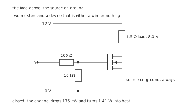
The load above, the source on ground, and a gate that has somewhere to stand.
This is the arrangement to reach for first, and the reason is in the bottom terminal. The source is bolted to ground and stays there in both states. The gate voltage the device responds to is measured against the source, so a gate driven against ground is a gate driven against the source, and an ordinary logic output can do it. Every complication in this lesson's fourth layer comes from moving that source somewhere else.
Worked example — What the switch takes out of the circuit
A 12 V rail driving 8.0 A means a load of 1.5 Ω, which absorbs 96 W.
With the gate at 10 V, the channel is 22 mΩ. Carrying 8.0 A, it drops 176 mV — 1.47 % of the supply — and turns 1.41 W into heat.
So the switch costs 1.45 % of everything the circuit draws. That is a good switch, and it is worth knowing what makes it one.
The two resistors around the gate are not decoration. 100 Ω in series limits the current the driving pin has to supply into the gate's capacitance at the instant of switching — the gate is a capacitor, and a capacitor connected straight to a voltage source draws whatever the wiring will allow. 10 kΩ from gate to ground holds the gate down when nothing is driving it, which matters more than it looks and gets its own figure later.
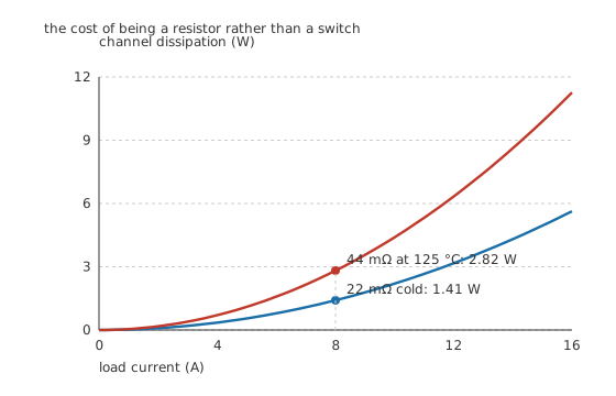
Doubling the current quadruples the heat, and heat raises the resistance.
The dissipation goes as the square of the current, and that has a sting in it. A switch comfortable at 8 A is not merely twice as warm at 16 A; it is four times as warm. And the resistance itself is not fixed: silicon's on-resistance rises with temperature, and by 125 °C this part's has risen by a factor of 2.0 to 44 mΩ. The same 8.0 A then dissipates 2.82 W, which heats it further. Sizing a switch on its cold datasheet number is the commonest way to be wrong about it.
Engineer
The gate voltage is most of the answer
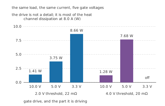
The same load, the same current, five gate voltages.
Two parts here, both n-channel, both rated for this job. One is a logic-level part: threshold 2.0 V, 22 mΩ at full drive. The other is a standard-threshold part: threshold 4.0 V, and a slightly better 20 mΩ at full drive. On a distributor's parametric search the second one looks like the better device.
Worked example — What each gate voltage actually buys
On-resistance follows the overdrive — the amount by which the gate clears the threshold — and it goes inversely with it, so halving the overdrive doubles the resistance.
The logic-level part at 10 V has 22 mΩ and burns 1.41 W. At 5.0 V its resistance rises to 58.7 mΩ and it burns 3.75 W. At 3.3 V, with the least overdrive of the three, it is 135 mΩ and burns 8.66 W.
The standard part at 10 V is the better device, at 1.28 W. At 5.0 V it is 120 mΩ and burns 7.68 W. At 3.3 V it is below its own threshold and does not turn on at all.
Six times the heat, from the same silicon, because of the drive. The part that wins on the datasheet loses badly in the circuit, and nothing about the comparison changes except one voltage.
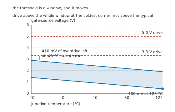
A threshold is not a number. It is a window, and it slides.
There is a second trap under the first one, and it is a specification trap rather than a physics one. The threshold on a datasheet is a range, not a value. This part is specified between 1.0 V and 2.5 V at 25 °C, and any device out of the bin may sit anywhere in that window. On top of that the threshold moves with temperature, falling at about -6.0 mV per degree.
Worked example — The two corners that decide it
Take the worst case in each direction across an operating range of -40 °C to 125 °C.
Turning on: the highest threshold you can be handed is the specified maximum at the coldest temperature — 2.89 V. A 3.3 V drive clears that by 410 mV, which is not enough overdrive to make a low on-resistance out of. A 5.0 V drive clears it by 2.11 V, which is.
Staying off: the lowest threshold you can be handed is the specified minimum at the hottest temperature — 400 mV. Anything that puts more than that on the gate risks turning the device partly on in a circuit that believes it is off.
The design rule falls out of the two corners: drive above the whole window at the cold end, and hold the gate below the whole window at the hot end. Designing against the typical threshold is designing against a number no particular device promises to have.
Professional
Above the load, and the gate that nobody holds down
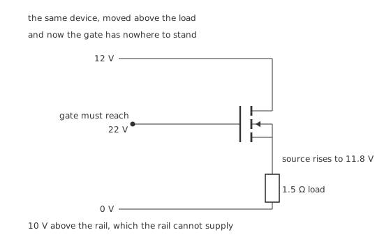
The same device, moved above the load, and now the gate has nowhere to stand.
Move the switch above the load — because you want the load's low side grounded, or because a fault to chassis should not energise it — and one thing changes: the source is no longer on ground.
Worked example — Why the high side is a different problem
Closed, the device drops 176 mV from the 12 V rail, so its source sits at 11.8 V.
The device responds to gate-to-source voltage, and it wants 10 V of it. So the gate has to reach 22 V.
That is 10 V above the highest voltage in the circuit. Nothing on the board can supply it, because the rail is the rail.
The standard answers all manufacture that extra voltage rather than finding it: a bootstrap capacitor charged while the switch is off and floated up with the source when it turns on, a small charge pump, an isolated supply, or a p-channel device that wants its gate below its source and so sidesteps the problem entirely at the cost of a worse on-resistance for the same die area.
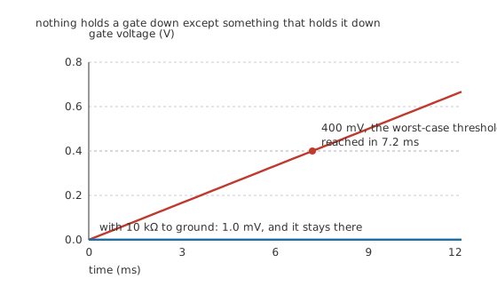
A gate with nothing attached is not at zero volts. It is at whatever the last thing to touch it left there.
Worked example — What a floating gate does
The gate is an insulated plate — 1.8 nF here — and nothing discharges it. A driver in reset, a connector not yet mated, a pin still in high-impedance at power-up: all of them leave it floating.
Now let 100 nA of leakage flow into it. The charge needed to lift it to the worst-case threshold of 400 mV is that capacitance times that voltage, and a steady current delivers it in 7.2 ms.
Seven milliseconds, and a switch nobody has commanded is conducting.
Put 10 kΩ from gate to ground and the same leakage produces 1.0 mV across it — a factor of 400 below the worst-case threshold. The resistor also gives the gate a discharge path with a time constant of 18 µs, so it reaches that resting value in the first fraction of a millisecond and stays there.
One resistor, a fraction of a penny, and the failure mode is gone. This is why the pull-down is in the first figure.
Four things that follow
Switching costs energy that this lesson has not counted. Everything above is conduction loss — the price of being closed. There is a second bill for every transition, while the device is passing current and holding voltage at the same time, and it grows with switching frequency. It has its own treatment, because the gate's capacitance turns out to set it.
An inductive load needs somewhere for its current to go. Motors, relays and solenoids do not stop instantly, and a switch that opens on one will see its drain fly above the rail until something clamps it. A MOSFET's own body diode helps in some topologies and not in others.
Two switches on the same load make a bridge. Put one above the load and one below, and you can pull it either way; put four in two pairs and you can reverse it. Everything in this lesson applies to each of them, plus one new rule: never let the two devices in a leg be on together.
And the bipolar comparison is not settled by any single number. The BJT as a switch has a roughly fixed saturation voltage, so its loss grows with current rather than with current squared — which is worse at low currents and better at very high ones. Where the two curves cross depends on the parts, and it is a real question rather than a rhetorical one.
Common mistakes
- Driving a standard-threshold part from 3.3 V logic — a device with a 4.0 V threshold does not turn on at all, and one with a 2.0 V threshold burns 8.66 W where it would have burned 1.41 W.
- Designing against the typical threshold — it is a window. The worst device you can be handed reaches 2.89 V at the cold end of its range, and no drive that fails to clear that is a drive.
- Sizing on the cold on-resistance — at 125 °C this part is 44 mΩ rather than 22 mΩ, and dissipates 2.82 W where the datasheet suggested 1.41 W.
- Leaving the gate floating — 100 nA into 1.8 nF crosses the worst-case threshold in 7.2 ms. A 10 kΩ pull-down holds it at 1.0 mV instead.
- Putting an n-channel device on the high side without a way to lift the gate — it needs 22 V on a 12 V rail, and the rail cannot supply it.
- Forgetting the square law — dissipation goes as the current squared, so a switch that is comfortable at one current is not merely twice as warm at twice that current.
Frequently asked questions
Why does the gate voltage change the on-resistance so much?
Because the gate builds the channel. On-resistance goes inversely with the overdrive — how far the gate clears the threshold — so a part at 22 mΩ with 8 V of overdrive is 58.7 mΩ with 3 V and 135 mΩ with 1.3 V. Same silicon, six times the heat at 8 A.
What is a logic-level MOSFET?
One specified to reach its rated on-resistance at a gate voltage a logic output can actually produce. The distinction is real: at 5.0 V the logic-level part here is 58.7 mΩ and the standard-threshold part is 120 mΩ, and at 3.3 V the standard part is below its 4.0 V threshold and never turns on.
Do I really need a gate pull-down resistor?
Yes, wherever the gate can be left undriven — at power-up, in reset, or with a connector unmated. 100 nA of leakage into a 1.8 nF gate reaches the worst-case 400 mV threshold in 7.2 ms. A 10 kΩ resistor turns that into a steady 1.0 mV, 400 times below the threshold.
Why is high-side switching harder than low-side?
Because the source moves. On the high side it rises to 11.8 V when the switch closes, and the device still wants 10 V between gate and source — so the gate has to reach 22 V, which is 10 V above the only supply the circuit has. A bootstrap capacitor, a charge pump, or a p-channel device is the usual way out.
How much does a good MOSFET switch cost the circuit?
Very little. At 8 A into a 1.5 Ω load, a 22 mΩ channel drops 176 mV — 1.47 % of a 12 V supply — and dissipates 1.41 W against the load's 96 W, so 1.45 % of everything drawn goes into the switch. The number gets worse quickly if either the drive or the cooling is neglected.