
Quick Answer
An H-bridge is four switches arranged as two legs across one supply, with the load between the legs' midpoints. Turning on one diagonal pair drives the load one way, the other diagonal drives it the other way, and turning both switches in a single leg on at once shorts the supply.
Intuition
Four taps and one pipe
Imagine a pipe with water in it and four taps: one from the reservoir to each end of the pipe, and one from each end of the pipe to the drain. Open the reservoir tap on the left and the drain tap on the right, and water runs left to right. Open the other two instead and it runs right to left. Same pipe, same reservoir, opposite direction — and nothing had to be rewired.
That is an H-bridge, and the letter is a picture of it: two vertical legs with the load lying across the middle.
The pairs that work together are the diagonal ones. Top-left with bottom-right, or top-right with bottom-left. One puts 23.7 V across the load and the other puts -23.7 V across it — the same magnitude, the opposite sign, from one supply with no negative rail anywhere.
And there is exactly one arrangement to be frightened of. Open the reservoir tap and the drain tap on the same side, and the reservoir empties straight down the drain without going anywhere near the pipe. In an H-bridge that is a direct short across the supply through two switches, it is called shoot-through, and it happens in tens of nanoseconds.
Almost everything else in this lesson is about that one failure and what it costs to prevent it.
Safety
An H-bridge drives things that move, store energy and get hot. A motor whose bridge switches on unexpectedly — from a floating gate, a reset, or a fault — will start turning with whatever is attached to it, and a stalled motor draws far more than its running current. Shoot-through destroys devices in the time it takes to read this sentence, usually with no warning and sometimes with enough energy to open a package. Every number in this lesson is an illustrative set chosen to make the arithmetic concrete — the supply, the winding, the device resistance and all four timings — and none is taken from any standard or any real part.
Practitioner
The circuit, and what it costs to be closed
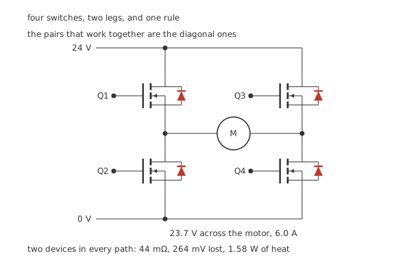
Two legs, one load across the middle, and four body diodes that come with the silicon.
The node to find on any bridge schematic is a leg midpoint: the place where the upper device's source, the lower device's drain and one end of the load all meet. There are two of them, and everything the bridge does is a statement about the voltage between them.
Worked example — What the bridge takes for itself
Current always passes through two devices in series, never one: down through the upper device on one side, across the load, and out through the lower device on the other.
So the conducting resistance is 44 mΩ, twice a single device's 22 mΩ.
At 6.0 A that costs 264 mV and 1.58 W of heat, leaving 23.7 V of the 24 V supply across the motor.
That two-device path is the bridge's standing tax. A single low-side switch pays half of it, which is one honest reason not to use a bridge where you do not need reversal.
Every device also arrives with a body diode — an unavoidable junction between its source and drain, anode on the source. On the upper devices that puts the anode on the midpoint and the cathode on the supply rail; on the lower devices, the anode on ground and the cathode on the midpoint. All four are therefore reverse-biased whenever the bridge is driving normally, which is why they are drawn but not doing anything yet. They become the whole story in the fourth layer.
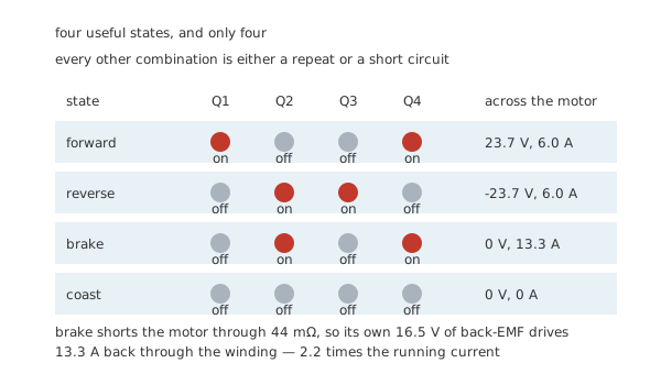
Four useful combinations, and every other one is a repeat or a short.
Brake and coast are not the same thing, and the difference matters. Coast turns everything off and lets the motor spin down against friction. Brake turns both lower devices on, which shorts the motor's own terminals together — and a spinning motor is a generator.
Worked example — What braking actually asks of the bridge
Running at 6.0 A with 23.7 V at its terminals, the motor's winding of 1.2 Ω drops part of that, and what is left is the back-EMF the rotation itself produces: 16.5 V.
Short the terminals through the two lower devices and that back-EMF is left driving current through the winding and 44 mΩ.
The result is 13.3 A — 2.2 times the running current, through devices sized for the running current.
Braking from speed is the harshest thing you can ask a bridge to do, and it is one command away from the gentlest.
Engineer
The failure the arrangement invites
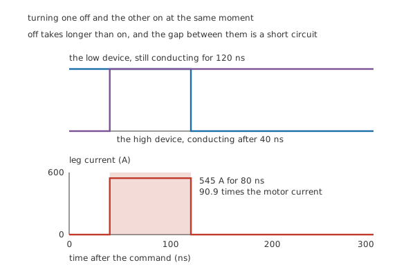
Off takes longer than on, and the difference is a short circuit.
Command one device in a leg off and the other on at the same instant and you have made an assumption: that the two events happen at the same time. They do not. Turning a MOSFET off takes longer than turning it on, because the gate charge has to be pulled back out through a driver that is usually weaker at sinking than at sourcing, and because the channel does not vanish the moment the gate starts falling.
Worked example — How bad the overlap is
This device takes 120 ns to stop conducting and 40 ns to start. Commanded together, the incoming device is fully on 40 ns in, while the outgoing one is still conducting until 120 ns — so both are on for 80 ns.
During that window the only thing between the supply and ground is the two channels: 44 mΩ. The current is 545 A, which is 90.9 times what the motor draws.
Each event dumps 1.05 mJ into the two devices. At 20 kHz that is 20.9 W of pure waste — more than ten times the bridge's honest conduction loss — in a package that was never asked to dissipate it.
And that is the survivable description. Devices in this situation usually fail before the average has time to mean anything.
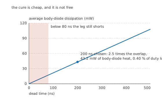
The cure is one delay, and it has a price.
The fix is dead time: a deliberate gap in which both devices in a leg are commanded off, inserted between turning one off and turning the other on. It has to be longer than the overlap it is covering, and longer again by whatever margin the device spread and temperature demand.
Worked example — Choosing the gap, and paying for it
The overlap to cover is 80 ns. Choosing 200 ns gives a margin of 2.5.
The price comes in two parts. During each gap the load's current is carried by a body diode dropping 0.90 V, which at 6.0 A is 5.40 W while it conducts. The gaps occupy 0.80 % of every cycle at 20 kHz, so the average is 43.2 mW.
The second part is not heat but accuracy: the load spends 0.40 % of every cycle not connected to the supply it was asked for.
Forty-odd milliwatts against 20.9 W of shoot-through is not a trade anyone has to think about. The margin is where the judgement is: too little and the leg still shorts, too much and the control loop is fighting a distortion it cannot see.
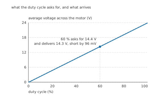
What the duty cycle asks for, and what arrives.
Speed control means switching a diagonal on and off quickly and varying the fraction of time it is on. The average across the load should be that fraction of the supply — a bare proportionality, and the dashed line is it. What actually arrives is that line shifted down, because every cycle loses the dead time's worth of volt-seconds.
Worked example — The offset the loop has to live with
At 60 % duty on a 24 V supply, the average asked for is 14.4 V.
The dead time removes 96 mV of it, every cycle, regardless of duty — so the average delivered is 14.3 V.
It is a constant offset, not a proportional error, which is what makes it awkward. At high duty it is a fraction of a per cent. Near zero duty it is most of the demand, which is why a bridge asked for very small motions often does nothing at all until the command clears the dead-time floor.
Professional
Where the current goes when nothing is on
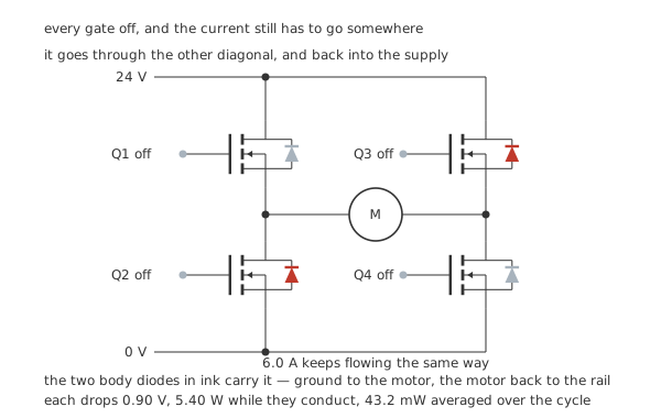
Every gate off, and the current still has to go somewhere.
Dead time raises a question that the schematic does not answer by itself. For those two hundred nanoseconds every switch in the bridge is off — and the load is a motor, which is an inductor, and an inductor's current does not stop because you stopped asking.
Worked example — Following the current with nothing turned on
The motor's 6.0 A was entering the left midpoint and leaving the right one. It must keep doing exactly that.
Entering the left midpoint: the only path is the lower-left device's body diode. Its anode is on that device's source, which is ground; its cathode is on the drain, which is the midpoint. Ground to midpoint is its forward direction, so it conducts.
Leaving the right midpoint: the only path is the upper-right device's body diode. Its anode is on that device's source, which is the midpoint; its cathode is on the drain, which is the supply rail. Midpoint to rail is its forward direction, so it conducts.
The other two body diodes are reverse-biased and carry nothing.
So the current runs from ground, through the motor, and back into the supply. The winding's stored energy is returned rather than burned, at a cost of 0.90 V in each of two diodes.
The pattern is worth memorising: the freewheel path is the body diodes of the other diagonal. The pair that was driving turns off; the pair that was off carries the current home. Drawn the other way round — with the driving diagonal's own diodes conducting — the picture looks perfectly reasonable and describes something that cannot happen.
Four things that follow
Body diodes are slow, and sometimes you add better ones. A MOSFET's intrinsic diode has a long reverse-recovery time, and at high switching frequencies the charge it takes to turn off becomes its own loss — and a source of the current spike that the next device sees at turn-on. Schottky diodes in parallel with the devices, which turn off almost instantly, are the usual answer. The same reasoning that governs a single flyback diode applies here four times over.
Half a bridge is a useful thing on its own. One leg drives a load one direction only, and that is a buck converter, a class-D output stage, or a single-direction motor drive. Everything in this lesson about shoot-through and dead time applies to a single leg unchanged, because a single leg is where the problem lives.
Integrated drivers exist because gate drive on the high side is hard. Both upper devices have their sources on a node that swings between ground and the rail, so their gates need to be driven relative to a moving reference — the problem the high-side switch introduces. A bridge driver chip supplies the bootstrap arrangement, the level shifting, and usually the dead-time generation as well, which is the more important half of what you are buying.
Current sensing turns a bridge into a control system. A shunt in the ground return of each leg, or in series with the load, gives the torque the motor is producing and the early warning of a stall. It is also the only practical protection against the failure mode this lesson opened with, because no fuse is fast enough for 545 A in 80 ns.
Common mistakes
- Turning on both devices in one leg — deliberately, or through a logic mistake, or through a gate that was left floating. 545 A for 80 ns, and no fuse in the world reacts to that.
- Setting dead time from the turn-on time — the number that matters is the difference between turn-off and turn-on: 80 ns here, not 40 ns. Then add margin for temperature and device spread.
- Adding far more dead time than needed — it is a constant 96 mV of error at every duty, which near zero duty is most of the command.
- Pairing the switches in the same leg instead of diagonally — the working pairs are top-left with bottom-right and top-right with bottom-left. Any other pair is either a repeat or a short.
- Treating brake as a gentle option — shorting the motor at speed puts 13.3 A through devices carrying 6.0 A a moment earlier, 2.2 times the running current.
- Assuming the freewheel current runs through the driving diagonal's diodes — it runs through the other diagonal's, and back into the supply.
Frequently asked questions
Why is shoot-through so much worse than an ordinary overload?
Because nothing limits it. In a leg with both devices on, the only resistance between supply and ground is the two channels — 44 mΩ — so a 24 V supply drives 545 A, which is 90.9 times the motor current. It also lasts nanoseconds, so no fuse or current limit reacts in time.
How much dead time should I use?
More than the difference between the device's turn-off and turn-on times, plus margin. Here that difference is 80 ns and the chosen dead time is 200 ns, a margin of 2.5. That costs 43.2 mW of body-diode heat and 0.40 % of the duty cycle — against 20.9 W if the gap is too small.
Why must the switch pairs be diagonal?
Because a diagonal pair puts the supply across the load in one direction: one device connects a midpoint to the rail, and the other connects the opposite midpoint to ground. Two devices in the same leg connect the rail to ground and never touch the load at all.
What carries the current during the dead time?
The body diodes of the diagonal that is not driving. With all four gates off, the load's current keeps its direction, so it enters one midpoint through the low-side diode on that leg and leaves the other through the high-side diode — running from ground, through the load, and back into the supply.
Does an H-bridge waste much of the supply?
Not much, but always twice what a single switch would. Current passes through two devices in series, 44 mΩ, so at 6.0 A the bridge drops 264 mV and dissipates 1.58 W, leaving 23.7 V of a 24 V supply for the motor.