
Use a MOSFET for switching: its gate costs nothing to hold, it turns off in tens of nanoseconds, and two of them share a load willingly. Use a bipolar transistor for small-signal gain, where it gives roughly thirty times the transconductance at the same current.
Intuition
Two ways to control a current
Both devices do the same job: a small thing at one terminal controls a large thing between the other two. They arrive at it differently, and every practical difference between them follows from that.
A bipolar transistor is controlled by current. Push charge carriers into its base and they cross into the collector circuit; stop pushing and it stops. Holding it on means keeping that base current flowing, continuously, for as long as you want the device on.
A MOSFET is controlled by voltage. Put charge on an insulated plate and the field it produces summons a channel; the plate is insulated, so once charged it stays charged and holding it on costs nothing at all.
That is the whole difference, and it explains most of the rest. The bipolar device's exponential relation between drive and output gives it enormous gain for tiny signals — and makes two of them impossible to match. The MOSFET's insulated gate gives it free steady-state drive and fast turn-off — and makes it a capacitor that has to be filled before anything happens.
Neither is better. They fail in different directions, and picking one is a matter of knowing which direction your circuit is pointing.
Practitioner
What it costs to keep each one on
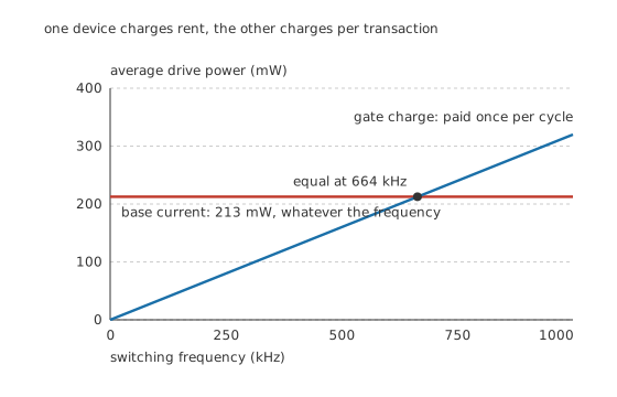
One device charges rent, the other charges per transaction.
Worked example — The drive bill for the same 5.0 A
The bipolar device. Switching 5.0 A on a 12 V rail at a forced gain of 10 — hard enough into saturation to be worth the name — needs 500 mA of base current. At 0.85 V that is 425 mW while it is on, or 213 mW at 50 % duty.
That bill arrives whether the device switches once an hour or a hundred thousand times a second.
The MOSFET. Its gate takes 32 nC to 10 V, and that charge is paid once per cycle. At rest it costs nothing.
The two are equal at 664 kHz. Below that frequency — which is nearly everything outside high-frequency power conversion — the gate is the cheaper terminal by a wide margin.
The conducting loss goes the other way at this operating point, and it is worth being honest about it. At 5.0 A the MOSFET drops 110 mV and dissipates 550 mW; the bipolar device holds 0.25 V regardless of current and dissipates 1.25 W. So the MOSFET wins here — but a resistive drop grows with current while a saturation voltage barely does, so at some higher current the order reverses. Where that crossing sits, and what it means, is a subject of its own.
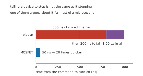
Telling a device to stop is not the same as it stopping.
Worked example — Why a saturated bipolar device is slow to release
Driving a bipolar transistor hard into saturation fills its base with charge carriers that have nowhere to be. Removing the base drive does not remove them; they have to recombine or be swept out.
That is storage time — 800 ns here, during which the device does not begin to turn off at all. Only then does the collector current fall, over a further 200 ns: 1.00 µs from command to off.
The MOSFET has no stored minority charge to clear. Pull the gate down and the channel goes with it: 50 ns, which is 20 times quicker.
The bipolar device can be made faster by not saturating it — a Schottky clamp, or simply less base drive — but the price is a higher on-state voltage, which was the reason to saturate it in the first place.
Engineer
What happens when one device is not enough
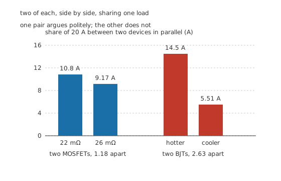
One pair argues politely; the other does not.
Paralleling is where the two device families behave most differently, and the reason is not manufacturing tolerance but the shape of each one's control law.
Worked example — Twenty amps, two devices, two outcomes
Two MOSFETs, one at 22 mΩ and a worse one at 26 mΩ, sharing 20 A. Two resistances in parallel split the current in inverse proportion to themselves: 10.8 A and 9.17 A, a ratio of 1.18.
And the imbalance corrects itself. The device carrying more gets hotter, its resistance rises, and it hands current back.
Two bipolar devices on a shared base, differing by 25 mV — a small mismatch by any standard. Collector current is exponential in base-emitter voltage, so at 25.9 mV that difference produces a current ratio of 2.63: 14.5 A against 5.51 A.
And that imbalance grows. The busier device gets hotter, its base-emitter voltage falls, so it takes still more of the current. Left alone the process runs away.
The cure is well known and it is not free: a small resistor in each emitter, which trades a voltage drop and some dissipation for negative feedback that the devices do not supply themselves.
This is why power MOSFETs are routinely paralleled and power bipolars are not — and why every large bipolar output stage has emitter resistors in it while its MOSFET equivalent often has nothing at all.
Professional
Where the bipolar device wins
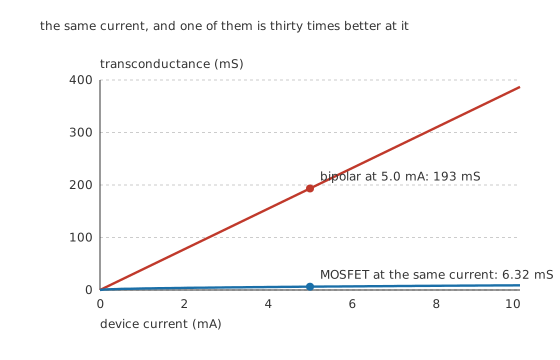
The same current, and one of them is thirty times better at it.
Everything so far has favoured the MOSFET. Move from switching to amplifying and the picture inverts, because the two control laws produce very different amounts of gain for the same current spent.
Worked example — Gain per milliamp
Transconductance is how much output current a small input voltage produces — the raw material of every amplifier.
The bipolar device. Its exponential law gives a transconductance of simply the current divided by 25.9 mV. At 5.0 mA that is 193 mS, and it rises in direct proportion to current with no reference to the device's size or process.
The MOSFET. Its square law gives twice the current divided by the overdrive. Reaching 5.0 mA with a device whose parameter is 2.0 mA per volt squared needs 1.58 V of overdrive, so the transconductance is 6.32 mS — and it rises only as the square root of current.
A factor of 30.6, at the same current, in favour of the bipolar device.
That single ratio is why bipolar input stages survive in precision analogue long after MOSFETs took over everything that switches. More gain per milliamp means less noise for the same power, and a transconductance that does not depend on device geometry means better matching between devices made together.
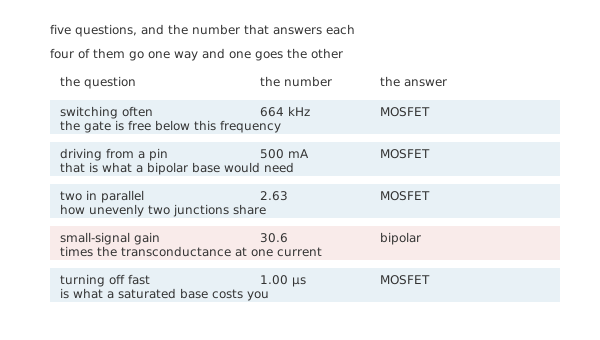
Five questions, and the number that answers each.
The decision, in order
- Is it a small signal? Then bipolar, almost always — 30.6 times the transconductance at the same current is not a margin any other consideration overturns.
- Does it switch often? Then MOSFET, up to 664 kHz and beyond. The gate is free at rest; a base is not.
- Is it driven from a logic pin? Then MOSFET. No pin sources 500 mA continuously.
- Does it need to turn off quickly? Then MOSFET — 1.00 µs of storage delay disqualifies a saturated bipolar device from anything fast.
- Does it need more than one device in parallel? Then MOSFET, unless you are prepared to add emitter resistors and the drop they cost.
And one question the list cannot settle: what the part costs and whether you can buy it. A small-signal bipolar transistor is among the cheapest components in existence and comes in packages nothing else does. That is a real engineering input, and it is why the answer is not always the one the numbers give.
Where this leads
The comparison is not a permanent verdict, because the device families keep borrowing from each other. The IGBT is an insulated gate driving a bipolar output — the drive advantages of one, the conduction advantages of the other. The Darlington pair attacks the bipolar drive problem from the other side by multiplying the gain until the base current is small. And modern MOSFET processes have pushed on-resistance so low that the conduction argument, once the bipolar device's strongest, now only survives at high voltages.
Common mistakes
- Driving a bipolar power transistor from a microcontroller pin — switching 5.0 A at a forced gain of 10 needs 500 mA of base current, continuously.
- Paralleling bipolar transistors without emitter resistors — 25 mV of mismatch splits 20 A as 14.5 A against 5.51 A, and the imbalance grows as the busier device warms.
- Choosing a MOSFET for a low-noise input stage — at 5.0 mA the bipolar device gives 193 mS against 6.32 mS, and no amount of process improvement closes a factor of 30.6.
- Expecting a saturated bipolar transistor to switch quickly — 800 ns of storage time passes before the current begins to fall.
- Comparing on-resistance to saturation voltage at one current — 550 mW against 1.25 W at 5.0 A says nothing about the answer at 50 A, because one loss grows with the square of current and the other only roughly in proportion.
- Assuming the MOSFET's free gate means free drive — it is free at rest and costs 32 nC per transition, which at high switching frequency becomes the larger bill.
Parts used in this topic
Frequently asked questions
Which one should I use to switch a load from a microcontroller?
A MOSFET, nearly always. The bipolar alternative needs 500 mA of base current to switch 5.0 A properly, which no logic pin supplies; the MOSFET needs 32 nC delivered once per transition and nothing at all in between.
Why can MOSFETs be paralleled but bipolar transistors cannot?
Because a MOSFET's on-resistance rises with temperature, so the device carrying more current hands some back — 22 mΩ against 26 mΩ splits 20 A only 1.18 to one. A bipolar device's base-emitter voltage falls with temperature, so the busier one takes more, and 25 mV of mismatch splits the same current 2.63 to one and growing.
Is a bipolar transistor ever the better switch?
At high current, potentially. Its saturation voltage is roughly fixed while a MOSFET's drop grows with current, so beyond some current the bipolar device dissipates less. At 5.0 A here the MOSFET is well ahead — 550 mW against 1.25 W — but that ordering does not survive to arbitrarily high currents.
Why do precision amplifiers still use bipolar inputs?
Transconductance. At 5.0 mA a bipolar device gives 193 mS against a MOSFET's 6.32 mS — a factor of 30.6 — because one is exponential in its drive and the other is square-law. More gain per milliamp means less noise for the same current, and the bipolar figure depends only on temperature rather than on device geometry, so devices match better.
At what frequency does the MOSFET's free gate stop being free?
Around 664 kHz for this pair, where the gate charge delivered every cycle costs the same 213 mW as the bipolar device's continuous base current. Below that the gate is cheaper; above it the comparison turns on switching loss rather than on drive power.
Knowledge check
What does it cost to keep each device switched on at 5.0 A? (Show answer)
Why is a saturated bipolar transistor slow to turn off? (Show answer)
How does 20 A divide between two devices in parallel? (Show answer)
Which device gives more gain at the same current, and by how much? (Show answer)
Compare the two devices' conducting losses at 5.0 A, and say what the comparison does not tell you. (Show answer)
One email a month from the bench
New circuits, lessons, part guides and calculators, on the first Sunday of each month.