
Quick Answer
The RMS value of an alternating waveform is the steady DC voltage that would deliver the same heating into a resistance. It is found by squaring the waveform, averaging those squares over a complete cycle and taking the root of the average. The peak divided by the square root of two applies to a sine only.
Intuition
Zero on average, hot to the touch
An alternating voltage spends as much of every cycle below zero as above it. Add its value up across a whole cycle and the total comes to nothing. Connect that same voltage to a heating element and the element gets hot, so the plain average is answering the wrong question.
Heating does not care which way the current went. Push charge one way through a resistor and it warms. Push it back the other way and it warms by the same amount again. Both halves of the cycle contribute, and they contribute together instead of cancelling.
What steady voltage, held constant, would warm the resistor at the same rate as this changing one? That question has a single-number answer, the RMS value, short for root mean square. A sine that peaks at 10 V heats a resistor as much as a steady 7.07 V would, and that is the figure to quote when heat is what the number is for.
The name spells out the arithmetic, read from the inside out. Square the waveform at every instant, which throws away the sign. Average those squares across one complete cycle. Take the square root of the average, which puts the answer back into volts.
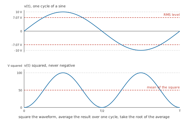
The lower trace never dips below zero, so it has an average worth taking. Its level, brought back through the square root, is where the RMS line on the upper trace sits.
Practitioner
Turning a peak into watts
Peak and RMS come off two different instruments. An oscilloscope draws the waveform, so the peak is read straight off the trace. A multimeter on its AC range returns one number, and that number is RMS. For a sine the two are locked together:
Once a waveform has been reduced to its RMS value, the power formulas carry over from DC untouched:
Compatibility with the DC expressions is the point of defining RMS at all. A resistive circuit can then be worked out using the same formulas that serve a battery, with no leftover factor to carry around.
The divisor, though, belongs to the shape. A symmetrical square wave sits at its peak for the whole cycle apart from its transitions, so its RMS value is the peak itself and there is nothing to divide by. A triangle or a symmetrical sawtooth sweeps steadily through everything between the extremes, and its RMS value is the peak divided by the square root of three. Common waveforms sets out the shapes side by side.
Worked example — Three shapes, one peak, one resistor
A generator drives a resistance of 100 Ω at a peak of 10 V.
Set to a sine, the output has an RMS value of 7.07 V, and the resistor dissipates 0.50 W.
Switched to a square wave of the same height, the RMS value becomes the peak itself, 10 V, and the dissipation doubles to 1.0 W.
Switched again to a triangle, the RMS value falls to 5.77 V and the resistor takes 0.333 W.
One height on the screen, three amounts of heat, and no change to the resistor.
Getting the convention wrong is a factor-of-two error in power, which is enough to cook a part sized on the wrong figure. A resistor's power rating is an RMS figure, as are the current ratings on wire, connectors and switch contacts. So is the ripple-current rating on an electrolytic capacitor, which is a heating limit set by the part's internal resistance and not a voltage limit at all.
Where a waveform is not one of the textbook shapes, the arithmetic has to be done properly, and that is what a true-RMS meter is for. An inexpensive meter is doing something else, taken up further on, and the difference shows up the moment a switching supply or a dimmer is in the signal path.
Engineer
Doing the operation the name spells out
The definition is an operation on the waveform, not a property of any particular shape. Take the instantaneous value at every point of one period, square it, average those squares across the period, and take the square root. Everything else here is that operation applied to a particular shape.
Squaring is the step that matters, and power dissipation is where it comes from. Power in a resistance goes as the square of the voltage across it, so the average power over a cycle follows the average of the square. Nothing else about the waveform enters. A waveform's mean and its mean square are independent quantities, which is how one of them can sit at zero while the other does not.
For a sine, the average of the square across a full cycle is half the peak squared. With a peak of 10 V that average is 50 V², and its square root is the 7.07 V already quoted. The root-two divisor is the square root of that one-half, and it carries no information about anything but a sine.
A rectangular pulse train needs no calculus at all. The waveform sits at its peak for a fraction D of each cycle and at zero for the rest, so the average of the square is D times the peak squared:
At a duty of 0.25 the same 10 V peak gives an RMS value of 5.0 V, and the resistor takes 0.25 W. A quarter of the cycle spent at full voltage buys a quarter of the square wave's heating. Duty cycle and PWM turns that into a way of controlling power.
Currents work the same way, since the operation is indifferent to what it averages, and an RMS current feeds the DC power expression the way an RMS voltage does:
Worked example — The same sine, read as a current
Across the resistance of 100 Ω, that sine drives a peak current of 100 mA.
The root-two divisor is a property of the sine's shape and not of the unit it is applied to, so the current's RMS value follows the same route to 70.7 mA.
That current, squared and multiplied by the resistance, accounts for 0.50 W, the same figure the voltage side gave.
The operation has conditions attached, and a real signal can break any of them.
The average has to run over a whole number of cycles. On a repeating signal that is easy, and an instrument achieves it by averaging over many cycles. On a signal that never repeats, "the RMS value" belongs to the window it was taken over, and a different window gives a different answer.
The published divisors describe idealised shapes. A real square wave has finite edges, a real triangle is bent, and a real pulse train has overshoot on every rise. The idealised figures hold while the transitions occupy a small share of the period, and they drift once the repetition rate climbs toward the circuit's own speed limit.
An RMS value says nothing about the peak. Two signals of equal RMS can reach very different extremes, so clipping, insulation stress and semiconductor breakdown all have to be checked against the peak. The ratio between them, the crest factor, is the bridge, and amplitude measures covers it.
RMS volts multiplied by RMS amps gives real power only into a resistance. Once there is any reactance in the load, voltage and current stop reaching their peaks together and the product becomes apparent power in volt-amperes. AC power and power factor take that up, and impedance is where the angle comes from.
Professional
Chopped waveforms and the meters that misread them
An inexpensive multimeter contains no squaring circuit. What it measures is the rectified average of its input, scaled by one fixed constant chosen so that a sine reads correctly. Show it a sine and the substitution is invisible. Show it anything else and the display is a rectified average presented as an RMS reading, with no marking on the instrument to say so.
Phase control is where that failure is easiest to see. A triac fires part-way into each half cycle and passes only the tail of the sine, which is how a lamp dimmer and a soldering-iron controller both work. The figures below are bench-scale arithmetic on the same small source as the earlier examples; the mains version of the same waveform belongs with AC and DC.
Worked example — An averaging meter shown a chopped sine
The generator still peaks at 10 V into 100 Ω, but conduction now begins 90° into each half cycle.
Half of every half cycle is gone, and so is exactly half the heating. The RMS value comes to 5.0 V, leaving 0.25 W in the resistor.
An averaging meter rectifies the same waveform and averages it to 3.18 V, then multiplies by 1.11, the constant that makes a sine come out right.
Its display settles at 3.54 V, low by 29.3 %.
The meter gives no warning, and the error runs the other way on a square wave, so there is no correction factor to apply and no way to guess which side of the truth a reading falls on. The quarter-duty pulse train above arrives at the same RMS value as this chopped sine from a trace that looks nothing like it, and warms the resistor by the same amount. Shape decides the reading on an averaging instrument; only heating decides the RMS value.
True-RMS instruments do the arithmetic instead of assuming the shape. The oldest kind heats a small element with the signal and compares its temperature against a DC-heated twin, which makes it exact by construction and slow. Analog implementations compute the square, the mean and the root with log and antilog stages. A digital meter samples the input and does the sums numerically. Each carries limits that its datasheet states: a bandwidth above which fast content is not counted at all, a maximum crest factor beyond which the front end clips, and often a tighter crest-factor limit near the top of the range. A very narrow pulse train will exhaust one of those on any of them.
Coupling decides whether a steady component is included. AC-coupled, an instrument blocks the DC term and reports the alternating part alone. DC-coupled, it includes both, and the two combine as squares, since the mean of the square of a sum carries a cross term that averages away when the parts are uncorrelated. Independent noise sources riding on a signal add the same way, as squares.
An RMS figure answers a question about heat and nothing else. An LED's brightness follows the average current through it, so a pulsed drive is judged on its average and not on its RMS value. A logic input and a comparator both respond to the instantaneous level against a threshold. A rectifier's reverse rating and a capacitor's voltage rating are peak figures. Reaching for RMS in those places produces a number that is correctly calculated and irrelevant.
Distorted current waveforms are where the distinction costs money. A load that draws its current in narrow bursts, which is what a capacitor-input rectifier does, has an RMS current far above what its average consumption suggests, so cables, transformer windings and switch contacts run hotter than the power figure implies. Cable sizing and protective-device selection therefore work from the RMS current, and the harmonics that come with such a waveform bring problems of their own. Where a supply serves many such loads, a standard governs what distortion may be injected at the connection point, and the applicable one has to be looked up for the market and the installation concerned.
Common mistakes
- Applying the sine's divisor to a measured waveform — a bench signal is rarely a clean sine once a switching supply, a dimmer or a rectifier sits in the path, and the root-two shortcut has no defined error on a shape it was never derived for.
- Averaging the waveform instead of its square — the plain average of a symmetrical alternating voltage comes to zero while its heating does not. Squaring first is what makes both halves of the cycle count.
- Trusting an ordinary multimeter on a chopped or pulsed signal — unless the display or the datasheet says true RMS, the instrument is scaling a rectified average by a constant chosen for a sine.
- Sizing a supply rail or an insulation margin from an RMS figure — clipping and breakdown happen at the peak. RMS answers the heating question and no other question at all.
- Calling RMS volts times RMS amps a wattage — that product is real power only into a resistance. With reactance present it is apparent power, quoted in volt-amperes.
- Reading RMS over a fraction of a cycle — the average has to cover a whole number of cycles, or run long enough that the leftover part does not matter. A short window on a slow signal gives a figure that wanders.
Frequently asked questions
What does RMS stand for?
Root mean square. The operations run in the reverse of the reading order: square the waveform first, take the mean of the squares over a cycle, then take the root of that mean. The name lists them from the outside in.
Why is the plain average of an AC waveform no use?
For a waveform that swings equally either side of zero it comes to zero, which says nothing about the heat the waveform delivers. Heating follows the square of the voltage, and a square is never negative, so the negative half of the cycle adds to the total instead of cancelling it.
Is a quoted mains voltage a peak or an RMS value?
An RMS value. Power engineering quotes RMS unless it states otherwise, so a nominal supply figure is RMS and the peak the insulation has to survive is higher by the square root of two.
Does a true-RMS meter include a DC component?
Only if it is DC-coupled. AC-coupled, it blocks the steady part and reports the alternating part alone. DC-coupled, it combines the two as squares, so a small ripple on a large DC level barely moves the reading.
Can two waveforms of different shapes have the same RMS value?
Yes, and they will heat a resistor identically. A rectangular pulse train and a phase-controlled sine can be set to the same RMS value while their traces look nothing alike, which is the point of the convention: it collapses shape down to the one property that decides heating.