
Quick Answer
Alternating-current power is quoted as three quantities. Real power, in watts, is the rate at which energy is consumed. Apparent power, in volt-amperes, is the RMS voltage times the RMS current, and it is what the supply and the cable must carry. Reactive power, in var, is the part that flows out and returns every cycle.
Intuition
Why volts times amps stops being watts
A resistor makes this easy. Multiply the voltage across it by the current through it and the answer is the heat it produces, in watts, which is all that electrical power means in a direct-current circuit.
Put a motor where the resistor was and the arithmetic stops working. Current still flows and a meter still reads amperes, but some of that current is not being consumed. The windings build a magnetic field during one part of the cycle and hand it back during the next. Energy leaves the supply, waits in the field for a few milliseconds and returns. Over a complete cycle it has done nothing to the shaft.
The wiring cannot tell the two apart. Cable warms on the total current it carries, borrowed and consumed alike, and a fuse or a breaker responds to that same total. The electricity meter is the one instrument in the installation that sees only the energy which never came back.
So a single alternating-current load needs more than one power figure. A load taking 5.0 A from a 230 V supply hands the installation 1150 VA to carry while consuming 920 W. Neither number is wrong. They answer different questions: what the wiring has to survive, and what the energy costs.
Practitioner
Two readings and a power factor
An RMS voltmeter and an RMS ammeter give the pair of readings everything else follows from. Their product is the apparent power, written S and given its own unit, the volt-ampere, to keep it visibly distinct from the watt.
Both readings have to be RMS values. Peak figures put a factor of two into the answer and mean nothing here.
Apparent power is an upper bound on what the load consumes. The real power, P, is the part of it that ends up as work or heat, and the fraction is the power factor: the cosine of the angle by which the current lags or leads the voltage. Nameplates state it, and impedance is the property of the load that sets it.
What is left over is the reactive power, Q, quoted in volt-amperes reactive and shortened to var. It is not the plain difference between the other two, because they sit at right angles to one another.
Worked example — A small single-phase motor
The motor draws 5.0 A from a 230 V supply, and its nameplate gives a power factor of 0.80.
Voltage times current puts 1150 VA through the supply cable and the protective device ahead of it.
Of that, 920 W is converted at the shaft and in the windings, and that is the figure the meter registers.
The third side of the triangle comes to 690 var, travelling out to the windings and back without being used up.
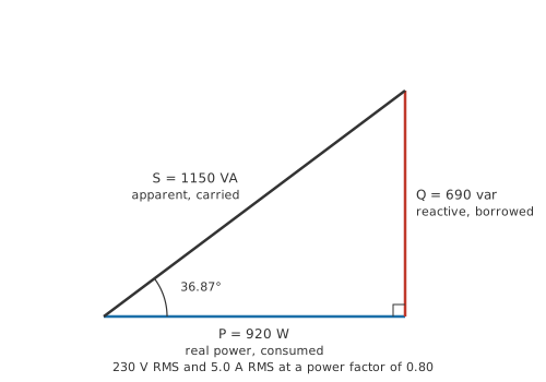
Drawn to scale, the triangle holds all three at once, and the shape says how much of the current is doing useful work. A resistive load collapses it to a horizontal line, apparent power equal to real power and the power factor at one. The angle opens as the load turns reactive, and the hypotenuse is always the longest side, so the supply is never asked for less than the load consumes.
Which figure to reach for depends on what is being sized. Conductors, contactors, switch contacts and protective devices are chosen against the apparent power, since all of them respond to current. Energy cost and cooling work from the real power. Label every figure with its unit as it is written down, because a number carried forward in watts when it was really volt-amperes will not announce itself later.
Safety
A mains-fed motor is the natural example for this subject, and it is also where taking the readings yourself stops being a beginner's exercise. Everything above was worked out from a nameplate and a nominal supply voltage. Measuring it means a voltmeter across live conductors and a current reading taken without breaking into them, which needs instruments rated for the circuit and the practices set out in electrical safety. A clamp meter reads the current through an insulated conductor without any connection to it, and it is the instrument to reach for first.
An ordinary multimeter gives the two RMS readings and therefore the apparent power. It cannot give the real power, because that needs the voltage and the current multiplied together instant by instant.
Engineer
Multiplying the waveforms instant by instant
Power at any instant is the voltage at that instant times the current at that instant, and alternating current changes nothing about that. What it changes is that both quantities are moving, and they are not moving together.
In the steady state at one frequency, the voltage is a sinusoid, the current is a sinusoid of the same frequency, and the phase angle between them is whatever the impedance imposes. Multiply two such sinusoids and the result separates into two pieces, both at twice the supply frequency.
One piece never reverses. It swells from zero to twice the real power and back, twice per cycle, and its average is P. That is the energy the load keeps. The other piece is a pure oscillation of amplitude Q with no average at all, out and back, out and back. That is the energy the load borrows. Added together they swing about P by the apparent power to each side, P and Q being the perpendicular sides and S the hypotenuse.
Worked example — One cycle of the motor's instantaneous power
The power factor of 0.80 is the cosine of a phase angle of 36.87°.
Instantaneous power oscillates about its average of 920 W at twice the supply frequency, swinging by the apparent power to each side.
It peaks at 2070 W, well over twice the average, and it dips to -230 W.
For as long as that figure is negative the load is not taking power at all. It is returning it, and the supply has to absorb what comes back.
So reactive power is an amplitude while real power is an average. They share a dimension and are read in quite different ways, and keeping their unit names apart is what stops anyone adding them together. The same reactive figure is the apparent power multiplied by the sine of the angle, the way the real power is the apparent power multiplied by its cosine.
The triangle has a second reading in ohms. Divide every side by the square of the current and the units change while the shape does not. Series parts share a current, and the same current that carries the real power through the resistive part of the load carries the reactive power through the reactive part, so the power triangle is the impedance triangle multiplied throughout by the current squared.
Worked example — The same load written as ohms
Supply voltage divided by current gives an impedance magnitude of 46.0 Ω.
The power factor scales that magnitude down to the resistive part, 36.8 Ω, and the sine of the same angle picks out the reactive part, 27.6 Ω.
Put the current squared against the resistive part alone and the answer is 920.0 W, the real power that the power-factor route already gave.
All of that depends on assumptions the derivation never had to state. Each one gives out somewhere.
A single frequency, and a sinusoid at it. Multiply two sinusoids of different frequencies and the product averages to zero over a cycle, so a voltage component only delivers real power to a current component at its own frequency. On a distorted waveform the arithmetic has to be done frequency by frequency and then summed, which is where harmonics enter.
Steady state. In the first cycles after a switch closes there are transients present that belong to no repeating cycle, and an average over "a cycle" is not yet a meaningful thing to take.
Linear, unsaturated components. A saturating transformer core or a rectifier distorts the current even when the voltage driving it is clean, and once the current is not a sinusoid there is no single angle to take a cosine of. The square-root expression still returns a number in that case, but it is no longer purely the borrowed energy the derivation above describes.
One phase. A balanced three-phase supply has the useful property that the three instantaneous powers add to a constant, which is one of the reasons power is generated and distributed that way.
Professional
Ratings, bills and distorted currents
A transformer, a generator and an uninterruptible supply all carry their rating in volt-amperes, and the reason is the same in all three. A winding heats on the current passing through it and its insulation is stressed by the voltage across it, and neither limit has any way of knowing when in the cycle the current arrives. A unit rated at one kilovolt-ampere delivers a kilowatt into a resistive load and appreciably less into a reactive one. Where a watt figure appears alongside, as it usually does on an uninterruptible supply, the two are separate ceilings and a design has to stay under both.
Cable, contactors and breakers follow the same logic, since current is what they respond to. Putting a figure on the cost of the extra current takes one line of arithmetic.
Worked example — What the borrowed current costs in the run that carries it
The run out to the motor has a resistance of 0.50 Ω, a figure chosen to keep the arithmetic clear and not taken from a cable table.
At 5.0 A that run dissipates 12.5 W.
Deliver the same 920 W at a power factor of one and the current falls to 4.0 A, which leaves 8.0 W in the same cable.
The two losses stand in the ratio 1.56, the inverse square of the power factor.
That last relationship is general: hold the real power fixed and every resistive loss between the generator and the load rises as the inverse square of the power factor, in the transformer windings as much as in the cable. The loss falls on whoever owns those, and metering arrangements follow the split. Electrical energy sold to a household is counted in kilowatt-hours, so a domestic bill sees the real power alone. Larger consumers are commonly billed on peak demand in kilovolt-amperes as well, or carry a charge attached to a poor power factor; the terms sit in the supply contract and vary between utilities and jurisdictions.
The remedy is to supply the reactive part close to where it is consumed instead of dragging it down the line. A capacitor takes its current a quarter cycle ahead of the voltage while an inductive load takes it a quarter cycle behind, so a capacitor sitting across a motor's terminals feeds the winding's borrowed current directly and the line upstream never carries it. Power factor and correction works through the sizing and motor run and start capacitors are the parts that do it. The same reasoning holds at grid scale, where real power travels hundreds of kilometres and reactive power is generated close to the loads that need it, one of the several constraints shaping how electricity reaches a building. The sign convention is worth learning early: a lagging, inductive load is quoted with positive reactive power and a leading, capacitive one with negative, so correction is described as a capacitor supplying var to a load that wants them.
Electronic loads break the picture in a different way. A rectifier feeding a reservoir capacitor conducts only near the peaks of the supply waveform, taking its current in short tall bursts. The fundamental component of such a current can sit almost in step with the voltage, putting the displacement factor close to one, while the total power factor stays poor because much of the current lives in harmonics that deliver no real power. The overall figure is the displacement factor multiplied by a distortion factor, and only that product is the ratio of watts to volt-amperes. What is left over once the real power is taken off the apparent power is then a mixture of true reactive flow and distortion, and the distortion part is sometimes separated out under its own name. What a load of this kind may inject back into a shared supply is governed by a standard, and which standard applies depends on the market and the size of the installation.
All of which puts a limit on what can be established with a meter in each hand. Real power needs the two waveforms multiplied point by point and averaged, which is what a power meter does internally and what two separate readings cannot reconstruct between them. Instruments that report a power factor differ in whether they give the displacement figure or the true ratio, and on a distorted load the two disagree. Which of them is on the display is a question for the datasheet.
Common mistakes
- Multiplying RMS volts by RMS amps and calling the answer watts — that product is the apparent power. It equals the real power only when the current is a sinusoid in phase with the voltage.
- Adding the volt-amperes of several loads together — real powers add directly and so do reactive powers, but apparent powers only add when every load shares the same angle. Add the two components separately, then take the hypotenuse.
- Sizing a cable or a breaker from the load's wattage — conductors and contacts heat on the current they carry, and the current follows the apparent power.
- Calling reactive power wasted energy — nothing is consumed by it, since the same energy comes back each cycle. The cost is the extra current, and therefore the extra resistive loss in everything that has to carry it.
- Trusting a good displacement angle on an electronic load — a rectifier can draw its current in phase and still present a poor power factor, because the current is a long way from sinusoidal.
- Losing the sign of the reactive power — the magnitude is the same whether a load lags or leads, and only the sign says which. Correction fitted to the wrong sign makes the power factor worse.
Frequently asked questions
What is the difference between watts and volt-amperes?
Watts measure the power a load consumes. Volt-amperes measure the product of the RMS voltage and the RMS current the supply has to provide, which is larger whenever the current is out of phase with the voltage or is not a sinusoid. The two are equal only for a purely resistive load.
Why are transformers and generators rated in VA rather than watts?
Their limits are heating in the windings, set by the current, and insulation stress, set by the voltage. Neither depends on the phase angle between them, so a rating expressed as the product of the two applies whatever load is connected.
What does the unit var stand for?
Volt-ampere reactive. It is dimensionally the same as the watt and is given a separate name to make it obvious that no energy is being consumed, only exchanged between the supply and the load's magnetic or electric field.
Does a domestic electricity meter charge for reactive power?
A household meter counts kilowatt-hours, which is real energy, so reactive power appears on the bill only indirectly through the losses it causes elsewhere. Larger installations are often metered on apparent power or peak demand as well, and the terms are set by the supply contract.
Can the real power ever exceed the apparent power?
No. The power factor is the ratio of the two and it cannot be greater than one, since real power is the average of a product whose amplitude is the apparent power. A calculation that produces more watts than volt-amperes has an error in it, usually a peak value used where an RMS value belongs.