
Quick Answer
Electricity reaches a socket through a chain of transformers. Power is generated at moderate voltage, stepped up for transmission, stepped down again at substations, and delivered at a few hundred volts. High voltage is used in between because line loss falls with the square of the voltage for the same delivered power.
Intuition
Tiers, not one long wire
A parcel does not travel from a factory to a doorstep on its own dedicated van. It goes onto a trunk route with thousands of others, then to a regional sorting office, then to a local depot, and only at the last step does it get a vehicle to itself. Each tier handles a lot at once, and each handover exists because what suits the long haul does not suit the last hundred metres.
The electricity network is organised the same way, for reasons that turn out to be arithmetic rather than administrative. Generation happens in a few large places. Consumption happens in millions of small ones. In between sits a hierarchy that carries a great deal of power over a long distance at high voltage, and progressively less power over shorter distances at lower voltages, until what arrives at a socket is something a person can safely use.
The device that makes each handover possible is the transformer, and its ability to trade voltage against current at constant power is the only reason the arrangement works at all. Before transformers, electricity had to be generated close to where it was used. After them, it did not.
What follows is why the middle of that chain runs at kilovolts, and what it would cost not to.
Practitioner
The arithmetic that decides everything
Power delivered is voltage times current times power factor. Loss in the cable is current squared times resistance. Since the same power can be delivered at any voltage you like by adjusting the current, and since loss depends on that current squared, the voltage choice is worth an enormous amount.
Worked example — 100 kW down two kilometres of cable, at 11 kV
Delivering 100 kW at a power factor of 0.95 over a line voltage of 11 kV takes a line current of 5.525 A. Checking that forwards through the power relationship returns 100 kW, as it must.
With 800 mΩ of resistance in each conductor, the three of them together lose 73.26 W.
Seventy-three watts, out of a hundred kilowatts. Now send the same power down the same cable at a voltage you could plug something into.
Worked example — The same power, the same cable, at 400 V
At 400 V the line current becomes 151.9 A, and the cable loses 55.4 kW — a factor of 756.2 more, and 0.554 of everything you were trying to deliver.
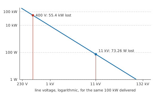
More than half the delivered power turned into warm cable. That is not a marginal inefficiency to be engineered away; it is a system that does not work. The ratio between the two losses is exactly the square of the voltage ratio, which is the entire argument for high-voltage transmission in one line.
Notice what the loss does not depend on. Not the voltage directly, only through the current it implies. Not the load's nature, only through the power factor that sets the current for a given real power — which is why power factor correction is worth money to a network operator rather than only to a consumer.
The transformer's part in this is easy to state and easy to underrate. It is the only component that can move power between two voltage levels without a proportional loss, and it does so with no moving parts and an efficiency that can exceed 99 per cent at grid scale. Every alternative anyone has tried — motor-generator sets, switched banks, resistive dropping — either wastes the difference or wears out. The reason alternating current won the argument over direct current in the 1890s is not that AC is better in any deep sense; it is that AC could be transformed and DC, at the time, could not.
There is a limit to how far the argument runs, and it is worth flagging now rather than letting it look like an oversight. Raising the voltage raises the insulation requirement, the clearance distances, the tower height and the switchgear cost, all of which climb steeply. The chosen voltage for any given link is where the falling cost of losses crosses the rising cost of insulation, which is why transmission voltage is a spectrum of standard levels rather than one very large number.
Engineer
The chain, and the second reason for the voltage
Loss is the argument everyone quotes. Voltage drop is the one that usually bites first, and it comes from the same current.
Worked example — What arrives at the far end
At 11 kV the cable drops 7.656 V, which is 0.000696 of the supply — undetectable.
At 400 V the same cable drops 210.5 V, or 0.526 of it. Over half the supply voltage is gone before it arrives.
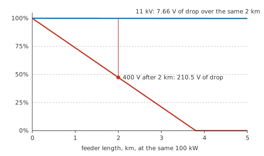
Equipment cares about voltage, not about efficiency statistics. A motor fed at half its rated voltage will not start; a supply fed at half its rated voltage will shut down or destroy itself trying. The permissible drop along a feeder is therefore a design limit long before the loss becomes economically interesting, and it is what sets how far a low-voltage distribution network can reach from its transformer.
That single constraint shapes the whole hierarchy.
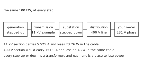
Generation happens at whatever voltage the machine is designed for, typically tens of kilovolts, since insulation and mechanical construction limit what a rotating machine can produce directly. A step-up transformer immediately raises it for transmission, where the distances are longest and the voltages highest. Substations step down in stages: transmission to sub-transmission, sub-transmission to distribution, and finally a local transformer to the voltage a building uses. Each stage exists because the optimum voltage falls as the distances shorten and the number of connection points multiplies.
Three-phase runs through nearly all of it, for the reasons three-phase basics sets out: three conductors carry three times the power of one for far less than three times the copper, and the total power is constant rather than pulsating. The final connection to a small consumer is usually one phase and a neutral, which is why a domestic supply is the phase voltage — 230.9 V here, off the 400 V line — while the distribution network around it runs at the line voltage.
The calculation above simplifies in two places that matter at grid scale. It treats the cable as pure resistance, whereas a real line has inductance, and a long overhead line has capacitance too; inductive drop can exceed resistive drop, which is why network voltage control uses reactive compensation rather than only thicker conductors. It also assumes a balanced load, and real distribution networks are not balanced: the neutral carries the difference, and the resulting voltage differences between phases are a routine operational problem rather than an anomaly.
Professional
What the last transformer has to do
The distribution transformer at the end of the chain is the one an electronics engineer is most likely to meet, and its specification follows from the same arithmetic.
Worked example — Sizing it
Delivering 100 kW at a power factor of 0.95 needs 105.3 kVA of apparent power, so a transformer must be rated for that rather than for the real power — the reason ratings are quoted in volt-amperes, as transformer losses explains.
Worked example — What it costs while nobody is using it
Core loss of 300 W flows whenever the transformer is energised. Over 8760 h that is 2628 kWh of energy, delivered to nobody.
Multiply that by the number of distribution transformers in a country and the standing loss becomes a national quantity. It is why distribution transformers are subject to minimum-efficiency regulation in most markets, why amorphous-core designs with very low core loss exist despite costing more, and why load factor — how much of the time a transformer is actually working — is part of the economic case rather than a footnote to it.
Safety
Everything above is arithmetic on a chosen example, and none of it was measured. The equipment it describes is another matter entirely.
Distribution and transmission equipment operates at voltages where proximity is enough. There is no safe way to inspect, test or work on it without training, authorisation and the correct equipment, and in every jurisdiction this is licensed work carried out under a permit system. A substation fence is not advisory.
At the domestic end, three points matter to anyone working on electronics. The supply at a socket is derived from that network, so its available fault current is far larger than a bench supply's and a short circuit is an arc rather than a click. The neutral conductor is not a safe conductor: it is a current-carrying conductor that happens to sit near earth potential, and it can rise well above earth under fault or under load imbalance. And the protective earth conductor is what makes an exposed metal case safe, so it is never the thing that gets disconnected to solve a problem.
Isolate, lock off and prove dead before touching anything mains-connected, in the sequence electrical safety sets out. Where a standard governs an installation — and one always does — it is the edition in force in your jurisdiction that decides, not a remembered rule.
Two developments are changing the picture the lesson has described, and both are worth knowing about even from the component end. Distributed generation, mostly rooftop solar, means power now flows in both directions along a distribution feeder that was designed to carry it one way, which turns voltage rise into a problem alongside voltage drop. And high-voltage direct current transmission, made practical by power semiconductors rather than by transformers, avoids the reactive-power and synchronisation problems of long alternating-current links, and is what makes very long submarine interconnectors possible. The transformer is not going anywhere, but it is no longer the only way to change a voltage level at scale.
Common mistakes
- Thinking high voltage reduces loss directly — it reduces the current needed for the same power, and loss follows the square of current. The voltage only matters through what it does to the current.
- Designing a feeder for loss and ignoring drop — the voltage at the far end usually violates its limit long before the loss becomes expensive, and equipment fails on voltage rather than on efficiency.
- Treating neutral as safe to touch — it carries current, and under fault or imbalance it can sit well above earth potential. It is a live conductor with a confusing name.
- Assuming a distribution network is balanced — real loads are not, the neutral carries the difference, and phase-to-phase voltage differences at the far end are routine.
- Modelling a long line as pure resistance — inductive reactance dominates the drop on many real lines, which is why networks control voltage with reactive compensation rather than only with copper.
Frequently asked questions
Why is electricity transmitted at high voltage?
Because for a given delivered power, a higher voltage means a proportionally lower current, and line loss follows the square of the current. Raising the voltage by a factor of ten cuts the loss by a factor of a hundred.
Why not generate at transmission voltage and skip a transformer?
Because a rotating machine's insulation and mechanical construction limit the voltage it can produce directly. Generating at tens of kilovolts and stepping up is cheaper and more reliable than building a generator for hundreds.
Why is domestic supply single-phase when the network is three-phase?
Because a house does not need three-phase power, and connecting different houses to different phases spreads the load across all three. The domestic supply is one phase and neutral, which is why it is the lower phase voltage rather than the line voltage.
What limits how far a low-voltage feeder can run?
Voltage drop, almost always. The loss becomes uneconomic eventually, but the voltage at the far end falls outside the permissible band first, and that is what sets the spacing of distribution transformers.
Does a transformer lose power even with no load connected?
Yes. Core loss is present whenever it is energised, and across a whole distribution network that standing loss is large enough to be regulated.
Why does high-voltage DC transmission exist if transformers only work on AC?
Because power electronics can now convert between AC and DC at grid scale. DC links avoid reactive-power and synchronisation problems over long distances, which makes them the practical choice for very long or submarine connections.