
Quick Answer
A transformer loses power in two places. Copper loss is heat in the winding resistance and rises with the square of the load current. Core loss comes from hysteresis and eddy currents in the iron, and stays almost constant whatever the load. Together they set efficiency.
Intuition
Warm with nothing plugged into it
Leave a plug-in transformer in a socket with nothing connected and come back an hour later. It is warm. No current is leaving the secondary, no work is being done, and yet the thing is quietly consuming electricity and turning it into heat.
That standing loss is the first of two quite different ways a transformer wastes power, and separating them is what this lesson is for. Copper loss is the obvious one: the windings are wire, wire has resistance, and current through resistance makes heat. It appears only when the transformer is loaded, and it grows fast — double the load current and the copper loss goes up four times.
Core loss is the one that explains the warm unplugged charger. The core is being magnetised and demagnetised a hundred times a second whether or not anything is connected, and that cycling costs energy every time round — for the same reason a paperclip warms up when you bend it back and forth, which permeability and core materials sets out. Core loss is there the moment the primary is energised and barely changes when a load appears.
The consequence is that a transformer's efficiency is not a single number. It is a curve, it depends on how hard the thing is being worked, and it is at its worst exactly where most equipment spends most of its life: lightly loaded.
Practitioner
Adding the watts up
Copper loss is ordinary resistive dissipation, once on each winding.
Worked example — Copper loss in a 48 VA transformer
The 48-turn secondary of 350 mΩ carrying 4.0 A dissipates 5.6 W.
The 920-turn primary of 22 Ω carries only 209 mA, so despite its much higher resistance it dissipates 958 mW.
Together, 6.558 W.
The two windings coming out comparable is not a coincidence: a transformer is normally wound so that both sides run at similar current density, which makes their copper losses similar by construction. If one side dominates, either the design is unbalanced or the transformer is being used at a voltage it was not wound for.
It is worth noticing which quantity drives that result. The high-voltage winding has many turns of thin wire and so a large resistance, but it carries very little current; the low-voltage winding is the reverse. Since loss follows the square of current and only the first power of resistance, the two effects come close to cancelling, and a designer who wants to reduce copper loss reaches for a bigger window area and thicker wire on both sides rather than trying to rebalance them.
Measuring the two losses separately is straightforward on a bench and worth knowing. Energise the primary with the secondary open and the input power is very nearly all core loss, because the magnetising current is small and its copper loss smaller still. Short the secondary and apply just enough primary voltage to circulate rated current, and the input power is very nearly all copper loss, because the flux and therefore the core loss are tiny at that reduced voltage. Those two measurements are the open-circuit and short-circuit tests, and between them they characterise a transformer without ever running it at full power.
Core loss is measured rather than calculated in practice, because it depends on the material, the peak flux density and the frequency in ways no single expression captures honestly. Take 2.4 W as an illustrative figure for a transformer of this size. Efficiency then follows directly:
Worked example — Efficiency at full load
Delivering 48.0 W while losing 6.558 W in copper and 2.4 W in the core, the transformer draws 56.958 W and runs at an efficiency of 0.843.
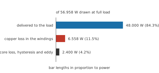
Eighty-four per cent sounds poor beside the ninety-nine per cent quoted for a large power transformer, and it is entirely normal for a small one. Losses scale roughly with surface area while throughput scales with volume, so efficiency improves steadily with size — the reason a grid transformer can afford to be very good and a doorbell transformer cannot.
Engineer
Two mechanisms in the core, and where efficiency peaks
Core loss is two effects with different physics that happen to arrive together.
Hysteresis loss is the energy spent walking the core round its magnetisation loop. Each full cycle traces a closed loop on the flux-density-against-field graph, the area enclosed by that loop is energy per cycle per unit volume, and multiplying by frequency gives power. It depends on the material's loop shape and on how far round the loop the flux is driven, which is why running a core at a lower peak flux density cuts hysteresis loss sharply, and why "soft" magnetic materials with narrow loops are what transformers are made of.
Eddy-current loss comes from the core being a conductor sitting in its own changing flux. By Faraday's law that flux induces voltages in the core itself, those voltages drive circulating currents, and the currents dissipate in the core's resistance. The remedy is to break up the conducting path: a mains transformer's core is built from thin laminations, each insulated from its neighbours, so the loops available to an eddy current are small and their induced voltages tiny. A ferrite is barely a conductor at all, which is why high-frequency transformers use ferrite rather than steel.
The two scale differently with frequency, and that difference decides which material a designer reaches for. Hysteresis loss rises roughly in proportion to frequency, since it is a fixed cost per cycle. Eddy loss rises roughly with the square of frequency, because both the induced voltage and the resulting current rise with it. At 50 Hz, laminated steel is fine. At 100 kHz it would be unusable, and ferrite wins — the trade permeability and core materials sets out from the material side.
Now put the two losses together against load and something useful appears.
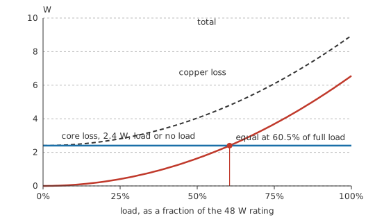
Copper loss follows the square of the load; core loss does not move. Efficiency is therefore worst at both ends and best somewhere in the middle, and a short piece of algebra locates it exactly: efficiency peaks where the two losses are equal.
Worked example — Where this transformer is happiest
The losses are equal at 0.605 of full load, which is 29.04 W delivered, with copper loss down to 2.4 W to match the core's.
Efficiency there is 0.858, against 0.843 at full load.
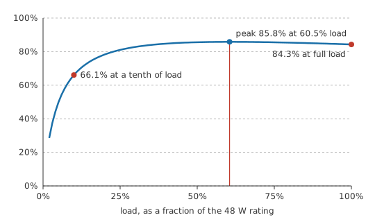
The peak is broad, which is the practically useful part: anywhere between about a third and full load, this transformer is within a couple of points of its best. The cliff is at the light-load end, and Layer 4 is about how much that costs.
Professional
Light load, standing loss and what to do about it
Worked example — A transformer barely working
At 0.10 of rated load the transformer delivers 4.8 W and its copper loss falls to 65.6 mW. Core loss is unchanged at 2.4 W, so efficiency collapses to 0.661.
A third of the input is now being thrown away, and the transformer is doing almost nothing. Scale that up and the arithmetic becomes an energy-policy question.
Worked example — Standing loss over a year
Left energised for 8760 h — a full year — that 2.4 W of core loss alone consumes 21.0 kWh.
Twenty-one kilowatt-hours per year, per device, for nothing at all. Multiply by the number of always-on adaptors in a household and it is the reason unloaded standby consumption became a regulated quantity in most markets, and why the old iron-cored plug-top adaptor was replaced almost everywhere by a switching supply that draws next to nothing when idle. Where efficiency limits apply, a standard governs what may be sold and how it must be measured; which standard depends on the market and the equipment class, and the applicable one is what to consult rather than a remembered figure.
These loss mechanisms carry four practical consequences.
Loss becomes temperature, and temperature is usually the real limit. A transformer's VA rating is a thermal rating, so the same core and windings will carry more in free air than in a sealed box, and derating for ambient temperature or for enclosure is normal rather than pessimistic. Winding resistance also climbs with temperature, so copper loss rises as the transformer warms and the two effects reinforce each other.
Sizing generously does not always help. A transformer running at ten per cent of its rating is less efficient than one running at sixty, so an oversized part wastes more standing power for the same delivered watts. Where the load is genuinely constant, sizing for the efficiency peak beats sizing for headroom.
Efficiency is quoted at a stated load, and it means nothing without one. Compare two transformers only at the same fraction of rating, and preferably at the fraction your design will actually use.
Distortion changes the answer. A rectifier drawing short high current peaks pushes far more copper loss than a resistive load of the same average power, because copper loss follows the RMS current rather than the average. That is one of several reasons a transformer feeding a full-wave rectifier runs hotter than its VA figure suggests, and why the rectifier's own reservoir capacitor is part of the transformer's thermal design.
Common mistakes
- Quoting efficiency without a load point — it is a curve, not a number. A transformer that is 84 per cent efficient at full load may be 66 per cent efficient at a tenth of it.
- Assuming an unloaded transformer costs nothing — core loss flows whenever the primary is energised, and over a year it adds up to real kilowatt-hours.
- Oversizing for safety — a lightly loaded transformer is a less efficient one, because the fixed core loss is being spread over less delivered power.
- Ignoring waveform when estimating copper loss — the loss follows RMS current, so a rectifier's peaky current draw heats the windings far more than its average would suggest.
- Treating the VA rating as a fixed property — it is a thermal rating, so enclosure, ambient temperature and mounting all change what a given transformer can actually deliver.
Frequently asked questions
Why is a transformer warm when nothing is connected?
Because the core is being magnetised and demagnetised at the supply frequency regardless of load, and both hysteresis and eddy currents dissipate energy every cycle. That core loss is present whenever the primary is energised.
What is the difference between copper loss and core loss?
Copper loss is resistive heating in the windings and follows the square of the load current. Core loss happens in the iron and is essentially independent of load, set instead by frequency and peak flux density.
Why are transformer cores laminated?
To interrupt the paths available to eddy currents. Thin insulated laminations reduce the area of each induced loop, cutting the induced voltage and the resulting circulating current, and so the loss.
At what load is a transformer most efficient?
Where copper loss equals core loss, which is usually well below full load. For the transformer worked through here that is about 60 per cent of rating, and the peak is broad enough that anything from a third of load upwards is close to it.
Why do small transformers have such poor efficiency compared with large ones?
Losses scale roughly with surface area while throughput scales with volume, so a bigger machine has proportionally less loss. A grid transformer above 99 per cent and a doorbell transformer below 90 are both entirely ordinary.
Does a switching supply avoid these losses?
It reduces them substantially rather than avoiding them. Running at tens or hundreds of kilohertz allows a far smaller core, and modern designs shut down almost completely at no load, which is why they replaced iron-cored adaptors for standby-heavy applications.