
Quick Answer
Permeability measures how readily a material carries magnetic flux. Relative permeability compares a material with empty space, and a ferrite may exceed a thousand. That multiplication is what makes cores worth using, and it holds only until the material saturates, after which it behaves no better than air.
Intuition
The paperclip that will not straighten
Bend a paperclip gently and it springs back. Bend it further and it comes back most of the way, keeping a little of the bend. Work it back and forth enough times and it warms up in your fingers and eventually breaks.
Magnetic materials behave remarkably like that, and the parallel is worth carrying because all three parts of it matter. A small applied field magnetises a core and the core lets go cleanly when the field is removed — the springy region. A larger field leaves the core still partly magnetised afterwards, which is remanence, and it is why a screwdriver that has been near a magnet stays slightly magnetic. Cycling a core back and forth wastes energy as heat every time round, which is why a mains transformer is warm and why transformer losses has a lesson to itself.
The reason any of this earns a place in an electronics course is the multiplication. Put a piece of ferrite inside a coil and the flux for the same current goes up by a factor of a thousand or more. Nothing else in ordinary engineering gives you a factor of a thousand for the cost of a lump of ceramic, and the whole of the rest of this department depends on it.
Practitioner
Relative permeability and the ceiling above it
The magnetising field H is what a coil applies, measured in ampere-turns per metre and independent of what is inside the coil. The flux density B is what results, and the material sets the exchange rate between them:
The constant μ₀ belongs to empty space; the dimensionless μ_r is the material's multiplier over it. Air, plastic, copper and aluminium all sit at essentially 1. Ferrites run from the tens into the thousands, and silicon steels higher still.
Worked example — A wound toroid, inside its linear region
A core of 100 mm mean magnetic path and 0.00015 m² cross-section carries 80 turns at 200 mA. The magnetising field is 160 A/m.
With a relative permeability of 1500, and μ₀ at 1.2566 µH/m, that gives a flux density of 302 mT and a flux of 45.2 µWb.
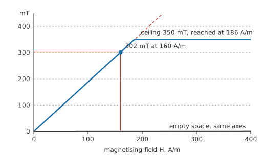
The straight line is only straight for a while. Every magnetic material has a saturation flux density, and for the ferrite above it is around 350 mT — an illustrative figure; the grade's datasheet is what governs. Above the knee, μ_r collapses towards 1 and the core has nothing left to give.
Notice how little of the graph the useful region occupies, and notice that the empty-space line is indistinguishable from the axis on these scales. Both observations are the same fact seen twice: a core buys you an enormous multiplier over a narrow range, and the narrowness is the price.
Choosing a family is mostly choosing where you want to sit on that trade. Manganese-zinc ferrites give high permeability and work well up to a few hundred kilohertz. Nickel-zinc ferrites give less permeability and keep working far higher, which is why they dominate suppression parts. Powdered iron and gapped composite cores give modest permeability with a very soft, gradual approach to saturation. Laminated silicon steel gives high permeability and high saturation flux density at mains frequencies, at the cost of weight and of losses that climb steeply with frequency.
Engineer
Magnetic circuits, and what a gap does
Flux behaves so much like current that the analogy has its own vocabulary. Ampere-turns drive flux the way voltage drives current, and the opposition is called reluctance:
Read those two together and they are Ohm's law with different names on the terms. The analogy is formal rather than poetic: reluctances in series add, reluctances in parallel combine reciprocally, and a magnetic circuit is solved with the same bookkeeping as an electrical one. It is not a perfect analogy — no energy is dissipated by reluctance, whereas resistance dissipates for a living — but as a calculation tool it holds.
Worked example — The same core, solid
The core above has a reluctance of 354 kA/Wb. The coil supplies 16.0 A of magnetomotive force, which drives 45.2 µWb round it — the same flux Layer 2 arrived at by the other route.
Now saw a millimetre out of it.
Worked example — One millimetre of air
The remaining ferrite path is 350 kA/Wb. The 1.0 mm of air, over the same cross-section, is 5.305 MA/Wb on its own.
In series those give 5.655 MA/Wb, so the same ampere-turns now drive only 2.83 µWb — a factor of 16.0 less. The gapped assembly behaves like a solid core of relative permeability 93.8, rather than 1500.
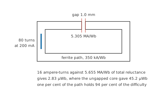
One per cent of the path length holds ninety-four per cent of the total reluctance. That single result explains an enormous amount of practical magnetics: why a relay needs far more current to pull in than to hold, why a transformer core's mating faces are ground flat and clamped, why a hairline crack in a ferrite core ruins it, and why the tolerance on a gap is tighter than the tolerance on anything else in the assembly.
The model's limits are worth stating plainly. It assumes flux stays inside the material, which a gap immediately violates: real gap flux bulges outward, an effect called fringing, and it makes the measured gap reluctance lower than calculated by a few per cent for a small gap and by much more for a large one. It assumes uniform cross-section and uniform permeability, neither of which survives a sharp corner. And it assumes μ_r is a constant, which Layer 2 has already shown to be true only within the linear region.
The last of those has a consequence worth chasing, because it inverts an intuition. An ungapped core's reluctance depends on μ_r, which changes with drive level, temperature and batch, so an ungapped inductor's value is only as repeatable as the ferrite. A gapped core's reluctance is dominated by air, whose permeability is a constant of nature, so the gap makes the assembly more predictable rather than less. Buying a gap costs inductance and buys tolerance, and in a production design that trade is usually worth making twice over.
There is also a reason the analogy stops short of being an identity, and it matters when you meet a magnetic circuit with two paths. Flux divides between parallel reluctances the way current divides between parallel resistances, so an E-core with a gapped centre limb and solid outer limbs really is a two-branch divider. But nothing in the magnetic circuit dissipates: the ampere-turns that drive the flux cost real power only because the winding has resistance, and the reluctance itself consumes nothing. Treating reluctance as a loss mechanism is the one way this analogy leads you astray.
Professional
Choosing and gapping a core
The gap calculation above looks like pure loss. It is the opposite, and understanding why is what separates picking a core from copying one.
Inductance is flux linkage per amp. Linkage is the turns times the flux, and the flux is the ampere-turns divided by the reluctance, so inductance works out as turns squared over reluctance — which means gapping divides the inductance by the same factor it divided the flux. Meanwhile saturation is reached at a fixed flux, and a higher reluctance needs proportionally more ampere-turns to reach it, so the saturation current is multiplied by that same factor.
Worked example — What the gap trades
Solid, the core gives 18.1 mH and saturates at 232 mA, storing 487 µJ at that point.
Gapped, it gives 1.13 mH and saturates at 3.71 A, storing 7.79 mJ — a factor of 16.0 more energy in the same lump of ferrite.
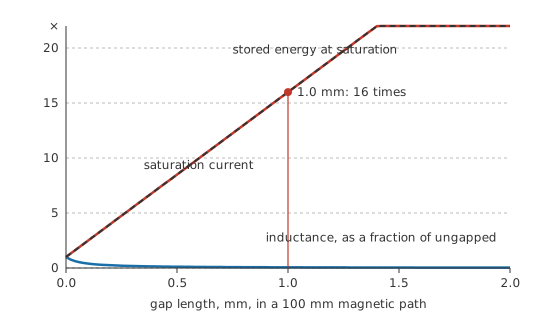
Energy stored goes as inductance times current squared, so dividing L by sixteen while multiplying I by sixteen multiplies the energy by sixteen. Almost all of that energy now sits in the gap rather than in the ferrite, which is exactly where you want it: air does not saturate, does not heat and does not age. Any inductor whose job is to store energy — the choke in a buck converter, the primary of a flyback transformer — is gapped for this reason, while a transformer that only couples energy from one winding to another is not, because there the gap would buy nothing and cost magnetising current.
Four selection criteria decide the rest, and they pull against each other.
Frequency sets the family before anything else does, because core loss climbs with frequency and the material determines how steeply. Temperature sets the margin: permeability, saturation flux density and loss all vary with it, saturation flux density falls as the core warms, and above the Curie temperature the material stops being magnetic altogether — a couple of hundred degrees for common ferrites, far higher for iron alloys, and always a figure to read rather than assume. Mechanical tolerance sets the repeatability, since the gap dominates the reluctance and a gapped core's inductance is a mechanical specification as much as a magnetic one. And permeability itself is usually the last thing to optimise, because in a gapped design the gap decides the answer and the material only has to be good enough not to matter.
Two things are worth carrying into the next component you spec. Manufacturers quote an A_L value, the inductance per turn squared, for exactly the reason the arithmetic above suggests: it packages the reluctance so you never have to compute it, and it is the number to design with. And ferrite is a ceramic, so it chips, cracks and is intolerant of clamping force — a core that has been dropped may look fine and measure ten per cent low, because a crack is a gap you did not intend. Inductor types works through the catalogue that results.
Common mistakes
- Treating relative permeability as a fixed number — it varies with flux density, with frequency, with temperature and with drive level. Datasheet curves exist because a single figure would be misleading.
- Designing at the saturation flux density — that is a limit, not an operating point. Loss, temperature rise and manufacturing spread all eat the margin, and the flux density falls as the core warms.
- Forgetting that the gap dominates — a millimetre of air in a hundred millimetres of ferrite holds most of the reluctance. Gap tolerance, not material tolerance, is what sets a gapped inductor's spread.
- Gapping a transformer core — a gap is for storing energy. In a transformer that only transfers energy it buys nothing and costs magnetising current, which is why flyback transformers are gapped and forward transformers are not.
- Assuming a cracked or chipped ferrite is fine because it still measures — a crack is an unintended gap, and it will move the inductance well outside tolerance while looking cosmetic.
Frequently asked questions
What does relative permeability actually mean?
It is the factor by which a material multiplies the flux density that a given magnetising field would produce in empty space. A relative permeability of 1500 means the same coil current gives 1500 times the flux density it would with an air core.
What is saturation, and how do I know I have reached it?
Saturation is the point where a core's magnetic domains are fully aligned and additional magnetising field produces almost no additional flux density. In a circuit it shows as inductance collapsing and current rising far faster than the applied voltage would suggest.
Why would anyone deliberately put a gap in a core?
To store energy. A gap raises the reluctance, which lowers the inductance and raises the current the core can take before saturating, and the net effect is that the assembly stores considerably more energy — nearly all of it in the gap.
What is reluctance?
The magnetic circuit's equivalent of resistance: how hard it is to drive flux round a path. It rises with path length and falls with cross-section and permeability, and reluctances in series add exactly as resistances do.
Why do ferrites and laminated steel exist side by side?
They occupy different frequency ranges. Silicon steel carries far more flux and suits mains frequencies; ferrite carries less but loses far less at high frequency, so switching supplies use ferrite and mains transformers use steel.
What is the Curie temperature?
The temperature above which a magnetic material loses its magnetic ordering and its relative permeability collapses towards one. Common ferrites reach it at a couple of hundred degrees, so it is a real design limit rather than a theoretical one.