
Quick Answer
A transformer passes energy between two coils wound on one magnetic core. Alternating current in the primary creates changing flux, and that flux induces a voltage in the secondary. Voltage divides in proportion to the turns on each winding, current divides in inverse proportion, and no wire joins the two.
Intuition
Two coils that never touch
A phone charger takes mains voltage in and delivers a few volts out. Somewhere inside it, that conversion happens across a gap: the two circuits share a magnetic core and nothing else. No wire crosses between them, and none needs to.
The mechanism is already familiar from electromagnetic induction. An alternating current in one coil makes a magnetic flux that rises and falls with it. A second coil wound on the same core sits in that changing flux, and a changing flux through a coil produces a voltage. Two coils, one core, and the mutual inductance between them does the rest.
What makes this genuinely useful rather than merely interesting is the ratio. The two windings need not have the same number of turns, and the voltage each one develops is proportional to its own turn count. Wind a hundred turns against a thousand and you have divided the voltage by ten. The arrangement has no preferred direction, so the same device steps up as readily as it steps down, and the entire electricity grid is built on that fact.
There is a price, and it is one you cannot negotiate. A transformer moves energy rather than making it, so whatever you gain in voltage you lose in current. The arrangement also depends on the flux changing, which means a transformer will not pass direct current at all, a limitation Layer 3 turns into a number.
Practitioner
Volts per turn, and where the current goes
Every winding on one core sees the same flux, so every winding develops the same voltage per turn. That single sentence gives both working relationships.
Worked example — A 230 V to 12 V mains transformer
With 920 turns on the primary at 230 V and 48 turns on the secondary, the secondary develops 12.0 V.
Current runs the opposite way. Since the transformer cannot create energy, the winding with the higher voltage must carry the lower current:
Worked example — The same transformer, loaded
Draw 4.0 A from the secondary and the primary draws 209 mA.
Voltage times current comes to 48.0 VA at the primary and 48.0 VA at the secondary, the same on both sides, as an ideal transformer requires.
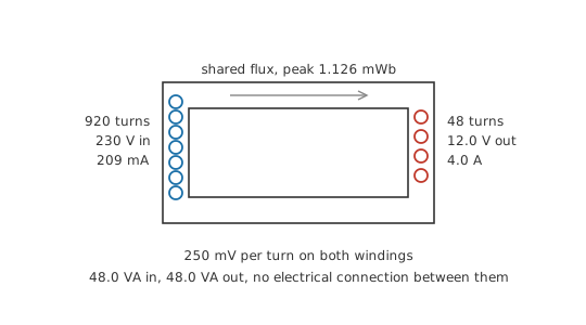
The equality of those last two figures is the whole economic case for the device. Nineteen times the voltage, a nineteenth of the current, and the same volt-amperes crossing from one side to the other.
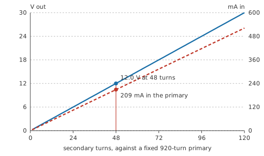
Both quantities move together as the turn count changes, which is the useful way to think about specifying one: choose the secondary turns for the voltage you want, and the current follows without any further choice on your part.
Beyond the ratio, the arrangement has a property no other component offers so cheaply: the windings are electrically isolated from one another, joined only by flux, so a fault on one side does not appear as a voltage on the other. That property is why mains-powered equipment is built around a transformer even where the voltage conversion is trivial, and it has a specification and a test standard behind it rather than being a happy accident of construction.
The coupling also works in both directions, which is less obvious and more useful than it sounds. A load on the secondary is felt by the primary, so an unloaded transformer draws almost nothing while a shorted one draws a great deal, and the primary side has no way to distinguish "my secondary is loaded" from "my supply is feeding a resistor". That is what makes the impedance-matching trick of turns ratio possible: choosing the turns changes what the source thinks it is driving.
One convention worth fixing before Layer 3. The winding fed by the supply is the primary and the one feeding the load is the secondary, and neither is a property of the transformer itself. Drive the 48-turn winding from 12 V and it becomes the primary, the 920-turn winding becomes the secondary, and 230 V appears across it. Transformers are symmetric; only the wiring decides which way the energy flows.
Engineer
Why the turns ratio comes out of Faraday's law
The flux in the core is common to both windings, so Faraday's law applies to each with only the turn count differing. For a sinusoidal flux, the RMS emf a winding develops is:
Only the turn count differs between the two windings in that expression, so dividing one by the other leaves the turns ratio and nothing else. The turns ratio is not an empirical rule; it is Faraday's law applied twice and divided.
Worked example — Where 920 turns came from
Take a core of 0.000938 m² worked to a peak flux density of 1.2 T, an illustrative figure for laminated silicon steel. That is a peak flux of 1.126 mWb.
At 50 Hz, the 920-turn primary develops 230.0 V and the 48-turn secondary 12.0 V — which is where Layer 2's numbers came from, rather than being assumed.
The primary's voltage spread over its turns comes to 250 mV each, and that figure belongs to the core rather than to either winding. Add a third winding of any turn count and it develops that many times 250 millivolts, without anyone recalculating anything.
Now look at what the same relationship says about frequency. The emf is proportional to frequency, so for a fixed applied voltage, halving the frequency doubles the flux the core has to carry. The core area is chosen for the lowest frequency the transformer will ever see, which is why a 50 Hz transformer is bulkier than a 60 Hz one of the same rating, and why running a 60 Hz transformer on a 50 Hz supply saturates it.
Push that argument all the way down and it explains the direct-current limitation exactly.
Worked example — The current a transformer draws doing nothing
The primary is a coil, and an illustrative 30 H of primary inductance presents 9.425 kΩ of reactance at 50 Hz. Across 230 V that draws 24.4 mA with no load at all — 0.117 of the full-load primary current.
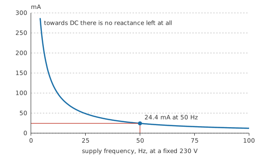
That curve has no bottom end. Reactance is proportional to frequency, so as the frequency falls towards zero the magnetising current rises without limit, and at DC the winding presents nothing but its own 22 Ω of copper. A 230 V DC supply across that primary would draw over ten amps and destroy the winding in seconds, and the secondary would produce nothing at all while it happened.
The magnetising current is also the first departure from the ideal model. It flows whether or not there is a load, it lags the applied voltage by ninety degrees, and it is the reason an unloaded transformer is not quite a dead weight on the supply. The second departure is that not all the primary's flux reaches the secondary; the fraction that escapes is leakage, quantified by the coupling coefficient that mutual inductance works through, and it is what Layer 4 turns into a voltage drop.
Professional
What the real thing does that the ideal one does not
The ideal transformer holds its secondary voltage steady whatever the load. Real windings have resistance, and the load current develops a voltage across it.
Worked example — Regulation on load
The secondary winding measures 350 mΩ and the primary 22 Ω. Referred through the turns ratio squared, the primary's resistance looks like 59.9 mΩ from the secondary side, so the load sees 410 mΩ in series with an ideal source.
At 4.0 A that drops 1.640 V, so the 12.0 V falls to 10.36 V — a regulation of 0.158.
Sixteen per cent is poor by modern standards and entirely typical of a small mains transformer, which is why a nominal 12 V transformer is often specified to give 12 V at rated load and rather more off load. Leakage inductance adds to that drop and gets worse with load current, which is why the figure quoted on a datasheet is measured rather than calculated.
Two more behaviours belong to real cores rather than to real windings. Inrush happens because the core's flux at switch-on depends on where in the cycle the supply was applied and on what remanence the core kept from last time; switch on at the wrong instant and the core saturates for the first few cycles, drawing a current far above the rated one. That is what blows the fuse in a device that was working perfectly yesterday, and it is why transformers are fused with slow-blow types. Core loss flows continuously whether or not there is a load, and together with copper loss it decides efficiency — the subject of transformer losses.
Safety
Every figure in this lesson is arithmetic on paper, and nothing here was built or probed. Three points about real transformers are safety matters rather than performance ones.
Isolation is a property of the construction, not of the word "transformer". A two-winding transformer separates its sides with insulation, and safety-rated types are built and tested to a standard for exactly that purpose. An autotransformer shares one winding between input and output and provides no isolation whatever, so its output is electrically connected to the mains, a distinction transformer types covers in full.
A transformer does not make a circuit safe to touch. An isolated secondary at 12 V is a low-voltage circuit, but the primary, its terminals and anything sharing its enclosure remain at mains potential, and an isolated secondary can still deliver enough current to cause a fire or an arc flash.
Anything with a mains primary is isolated, locked off and proved dead before it is opened, and in most jurisdictions work on mains-connected equipment is licensed. Electrical safety sets out the sequence.
Three selection points close the subject. Rating is quoted in volt-amperes rather than watts, because a transformer's limits are set by winding heating and core flux, neither of which cares about the load's power factor. Frequency is a hard specification rather than a preference, for the saturation reason Layer 3 gave. And the way a transformer fails matters: an open primary is quiet and harmless, while a shorted turn is not, and a shorted turn is what an overheated or damaged transformer usually produces.
Where the secondary output goes next is rectification, the turns ratio's use for matching impedances is turns ratio, and the grid-scale version of this lesson is how electricity reaches your home.
Common mistakes
- Assuming any transformer isolates — an autotransformer shares a winding and isolates nothing. Isolation is a construction and a rating, not a consequence of the name.
- Expecting a transformer to pass DC — the secondary voltage comes from changing flux. A DC supply across the primary produces no output and burns the winding on its own resistance.
- Running a 60 Hz transformer on 50 Hz — the flux for a given voltage is inversely proportional to frequency, so the core saturates and the magnetising current climbs steeply.
- Reading the no-load secondary voltage as the rating — a small transformer's output falls several per cent under load, and the quoted figure is usually the loaded one.
- Fusing a transformer for its running current — inrush at switch-on can be many times the rated current, so a fast fuse will nuisance-blow at some point.
Frequently asked questions
How does a transformer transfer power with no electrical connection?
Through the magnetic flux the two windings share. Alternating current in the primary makes changing flux in the core, and changing flux through the secondary induces a voltage in it. The two circuits are joined magnetically and not electrically.
Why does the current go down when the voltage goes up?
Because energy is conserved. A transformer transfers power rather than creating it, so an ideal one delivers the same volt-amperes on both sides, and multiplying the voltage requires dividing the current by the same factor.
Why will a transformer not work on DC?
The induced voltage depends on the rate at which flux changes, and a steady current makes a steady flux. The secondary produces nothing, while the primary presents only its own winding resistance to the supply.
What is magnetising current?
The current the primary draws to establish the core's flux, present with no load connected. It lags the applied voltage by ninety degrees and is largely reactive, so it costs volt-amperes rather than watts.
Why is a transformer rated in VA rather than watts?
Because its limits are winding heating and core flux, which depend on current and voltage separately rather than on their product with power factor. A load drawing 100 VA at a poor power factor stresses the transformer exactly as much as one drawing 100 VA at unity.
Why does a transformer hum?
Magnetostriction makes the core laminations change shape slightly as the flux cycles, and any looseness lets them move against each other. At 50 Hz the flux reverses a hundred times a second, so the hum is at twice the supply frequency.