
Quick Answer
Transformers divide by construction as much as by ratio. An isolation transformer has separate windings and no conductive path between them. An autotransformer taps a single winding, so it is smaller but offers no isolation. A current transformer measures current by encircling the conductor carrying it.
Intuition
Three devices that look alike
Put an isolation transformer, an autotransformer and a current transformer on a bench and a casual glance finds the same thing three times: a core, some copper, two pairs of terminals. What separates them is not the ratio but how the windings are arranged, and the differences are the kind that matter rather than the kind that are merely interesting.
The isolation transformer is the one how transformers work described: two separate windings on one core, joined by flux and by nothing else. Often it has a ratio of one to one, which sounds pointless until you notice that the ratio was never the point. What you are buying is the absence of a conductive path.
The autotransformer does the same voltage-changing job with a single winding and a tap partway along. It is smaller, cheaper and more efficient than a two-winding transformer of the same rating, and it gives no isolation at all, because the output shares a connection with the input.
The current transformer inverts the usual arrangement. Its primary is the conductor whose current you want to measure — often a single pass through the core, or the cable itself — and its many-turn secondary delivers a scaled-down copy of that current into a small resistor. It is how a clamp meter reads alternating current without breaking the circuit.
The distinction that matters most is the second one, and it is a safety matter rather than a performance one: a device labelled "transformer" does not necessarily isolate anything.
Practitioner
What each one actually does
The isolating type is the simplest to specify because the ratio is usually one.
Worked example — A 1:1 isolating transformer
With 1150 turns on both windings and 230 V in, the output is 230 V, at 200 mV per turn on each side.
Same voltage, same current, no gain of any kind — and a complete break in the conductive path, which is the entire product.
The autotransformer replaces the second winding with a tap.
Worked example — An autotransformer stepping 230 V to 200 V
Delivering 5.0 A at 200 V is 1.0 kVA of throughput, which the 230 V input supplies at 4.348 A.
The tap sits at 1000 turns of the 1150, and the section below it carries only 652 mA, the difference between the two currents.
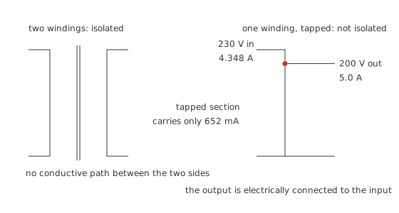
That difference current is the whole saving. Most of the load current never passes through a transformed winding at all; it flows straight from input to output through the shared conductor, and only the small remainder has to be handled magnetically.
The current transformer works from the other end, treating the measured conductor as a one-turn primary.
Worked example — A 1000:1 current transformer
With 1 primary turn and 1000 secondary turns, a primary current of 100 A gives a secondary current of 100 mA.
Across a burden resistor of 10 Ω that reads as 1.0 V, and the whole measurement costs the secondary 100 mW.
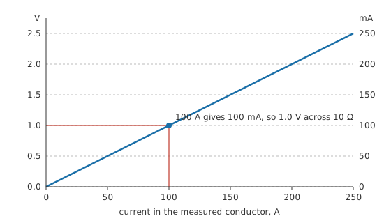
One volt per hundred amps, from a device that touches nothing and dissipates a tenth of a watt.
The ratio convention is worth noting before it causes trouble. A current transformer is quoted the opposite way round from a voltage transformer: 1000:1 here means a thousand secondary turns to one primary, and therefore a current division by a thousand rather than a multiplication. Commercial CTs are usually labelled by their current ratio instead, 100:0.1 or 100:5 amps, which removes the ambiguity at the cost of a longer label.
The other thing to notice is that all three of these devices obey exactly the relationships the previous two lessons established. No new physics appears in this lesson at all. What changes is which terminal the load hangs on, which winding the supply drives, and whether there is a conductive path between them, and those three choices are enough to produce three components with entirely different jobs and entirely different failure modes.
Engineer
Why the savings and the hazards both come from the construction
The autotransformer's advantage is worth quantifying, because it explains both when to use one and when not to bother.
Worked example — How much power actually gets transformed
The winding above the tap sees the 4.348 A input current across the 230 V to 200 V difference, which is 130.4 VA of transformed apparent power against 1.0 kVA passing through — a factor of 7.67 smaller.
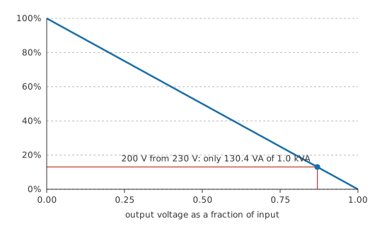
The curve is the reason autotransformers are used for small voltage adjustments and not for large ones. Trimming 230 V to 200 V transforms thirteen per cent of the power, so the magnetics can be roughly an eighth the size. Stepping 230 V down to 12 V would transform ninety-five per cent of it, and the autotransformer would be almost the same size as a two-winding one while giving up isolation for nothing.
The current transformer's constraint comes from ampere-turns rather than from volts. In normal operation the secondary current opposes the primary's magnetomotive force almost exactly.
Worked example — The balance that keeps a CT working
The primary supplies 100 A of magnetomotive force. The secondary's 100 mA through 1000 turns opposes it with 100 A, so the core carries a net 0.0 A of driving mmf and almost no flux.
That near-perfect cancellation is what lets a current transformer have a small core and stay accurate. It also means the burden resistor is not optional. Open the secondary and the opposing ampere-turns vanish, leaving the full primary mmf to magnetise the core alone. The core saturates hard, the flux slams from one extreme to the other twice a cycle, and Faraday's law applied to a thousand turns and a very fast flux change gives a secondary voltage limited only by the core's saturation behaviour and the winding's insulation. The figure is genuinely dangerous on an installed CT, and it is why every current transformer terminal block carries a shorting link.
The ideal CT model breaks down in two places. Accuracy depends on the magnetising current being negligible beside the reflected primary current, so a CT loses accuracy at the bottom of its range where the two become comparable, which is why an instrument transformer's accuracy class is quoted over a stated fraction of its rating rather than all the way to zero. The burden also has to stay small: a large burden resistance means a large secondary voltage, which means real flux in the core, which means the cancellation is no longer near-perfect and the ratio drifts. That is why burden is specified in volt-amperes on instrument transformers, and why adding a long cable run between a CT and its meter is a measurement decision rather than a wiring one.
Professional
Choosing a type: the one distinction that is not negotiable
Safety
Every number in this lesson came out of a calculator rather than off a bench, and the mains-level examples were never built. Three points here are safety matters rather than design preferences.
An autotransformer does not isolate. Its output is conductively connected to its input, so a mains-fed autotransformer's output is at mains potential with respect to earth however low its output voltage reads. A variable autotransformer set to 12 V is still a mains-connected circuit. Where isolation is required for safety, only a transformer built and rated as an isolating or safety isolating type provides it, and the standard that governs its construction is stated on the part.
A current transformer's secondary is never opened while its primary is energised. Removing the burden leaves the primary's ampere-turns unopposed, the core saturates, and the secondary develops a voltage that is dangerous to people and destructive to insulation. Short the secondary before disconnecting anything, using the shorting link provided for the purpose.
Isolation does not make a circuit safe to touch. It removes the earth-referenced shock path; it does not remove the voltage between the isolated conductors, nor the energy available in a fault. Isolate, lock off and prove dead before working, as electrical safety sets out, and treat mains-connected work as licensed work.
Beyond those three, selection comes down to what the transformer is for.
An isolating transformer is specified when a conductive break is required: separating a device under test from the mains supply so that a probe ground does not create a fault path, breaking a ground loop between audio equipment, or providing the isolation that a medical or a safety-extra-low-voltage supply demands. Its ratio is often one, and the specification that matters is the isolation rating rather than the turns.
An autotransformer is specified where the voltage change is modest and isolation is genuinely not required: trimming a supply voltage between regional standards, starting a large motor at reduced voltage, or providing an adjustable output as a variable autotransformer. The size and efficiency advantages are real, and the isolation loss is absolute.
A current transformer is specified by ratio, burden and accuracy class, plus a rated short-time current for fault conditions. Its cousins are worth knowing: a Rogowski coil measures the same thing with an air core and an integrator, handles very large currents without saturating, and cannot measure DC; a Hall-effect sensor can measure DC but drifts.
Construction affects all three. A toroidal core wastes less, hums less and radiates far less than a stacked-lamination one, at higher cost and with a fiercer inrush. Planar transformers replace wire with copper on a circuit board for high-frequency switching supplies. Where several separate secondary windings are provided, they are separate for a reason, and treating one as though it were another's continuation is a good way to defeat whatever isolation was designed in. The component-level treatment continues in transformers as components.
Common mistakes
- Treating a variable autotransformer as an isolation transformer — it is not one, and its output stays at mains potential relative to earth however low the dial is set.
- Opening a current transformer's secondary under load — the core saturates and the secondary develops a dangerous voltage. Short it first, every time.
- Using an autotransformer for a large step-down — the size and efficiency saving disappears as the ratio departs from one, so you give up isolation and gain very little.
- Ignoring a CT's burden specification — too large a burden puts real flux in the core, and the ratio drifts away from its nominal value long before anything looks wrong.
- Assuming multiple secondaries can be treated as one winding — they are separated deliberately, and joining them can defeat the isolation the transformer was chosen for.
Frequently asked questions
What is the difference between an isolation transformer and an autotransformer?
An isolation transformer has two electrically separate windings with no conductive path between input and output. An autotransformer uses one winding with a tap, so input and output share a connection and there is no isolation.
If the ratio is 1:1, what is an isolation transformer for?
The isolation itself. Breaking the conductive path removes the earth-referenced shock and fault path, which is why it is used for test benches, for breaking ground loops, and wherever a standard requires separation.
Why is an autotransformer smaller than a two-winding one?
Because only the power corresponding to the voltage change is transformed magnetically. The rest passes straight through the shared conductor, so the core and windings handle far less than the throughput.
Why must a current transformer's secondary never be left open?
Its secondary current normally cancels the primary's magnetomotive force almost exactly. Open the secondary and nothing opposes the primary, the core saturates, and the many-turn secondary develops a very high voltage.
What is a burden resistor?
The small resistance a current transformer's secondary drives, converting the scaled current into a voltage a meter can read. It must be small enough to keep the secondary voltage low, and its value is part of the measurement's calibration.
Can a current transformer measure DC?
No. It works by induction and so responds only to changing current. Measuring direct current without breaking the circuit needs a Hall-effect sensor or a fluxgate instead.