
Quick Answer
A mains transformer is sold by its VA rating, which is the load at which its own losses raise it to a permitted temperature. Its secondary voltage is quoted at that load; unloaded it reads higher, and the difference is the regulation.
Intuition
You are buying a temperature rise
Ask what a transformer is and the answer is easy enough: two windings on a core, and the ratio of the turns sets the ratio of the voltages. That is the physics, it is correct, and it is available in every textbook.
Ask what a particular transformer is and the answer is a catalogue line, and the catalogue line does not mention turns at all. It says something like twenty volt-amps, twelve volts, and gives a part number.
The turns ratio has become invisible because it is not the thing that is scarce. Any number of turns can be wound. What cannot be arranged is for a lump of copper and iron to get rid of the heat its own losses make, and that is what the rating is really about. Push more current through the windings and they get hotter; keep pushing and the insulation between the turns starts to age, then fails, and a winding shorts to itself or to the core.
So the VA figure is a thermal limit with an electrical unit. It is the load at which the transformer settles at whatever temperature rise the manufacturer decided its insulation could live with, in whatever airflow they assumed.
The other thing the catalogue line does not tell you plainly is that the secondary voltage on the label is not the voltage you will measure. That takes the next layer.
Safety
The primary side of a mains transformer is at mains potential and it is lethal. It stays lethal with the secondary disconnected, with the equipment apparently off, and for as long as the plug is in, because the only thing between the live conductor and your hand is insulation you cannot inspect. The isolation is the reason to fit one — in the equivalent circuit below the two windings share no electrical node — but isolation protects the secondary side, not you, and it is exactly as good as the transformer's construction and no better. A cracked bobbin, a winding that has overheated, or a part not built for mains isolation duty removes it silently. Every number in this lesson is an invented illustration and none of them is a specification: insulation class, isolation voltage, creepage and the approvals that go with them are attached to standards and to a specific part, and a transformer for a mains input has to be one built and approved for that job. The one number here worth taking away is the inrush: this example's 3.97 A first peak is 29.3 times its steady peak, which is why a fuse chosen for the running current will blow when the equipment is switched on and why fuse type, not just fuse rating, is part of the design.
Practitioner
Two secondary voltages, and only one of them is on the label
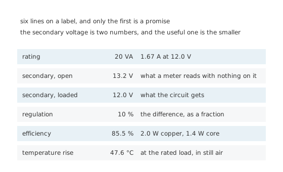
Six lines on a label, and only the first is a promise.
Take the part apart with a meter and you find two secondary voltages. With nothing connected the secondary reads 13.2 V. With its rated load on it, the same secondary reads 12.0 V, and that is the number printed on the label.
Worked example — What the load takes out of it
The rating is 20 VA, so at 12.0 V the secondary is delivering 1.67 A.
Between no load and that load the secondary has dropped 1.2 V, which is a regulation of 10 %.
The turns ratio is only visible with nothing connected, where the windings' resistances are carrying no current: 230 V over 13.2 V is 17.4 to one. Referred through that ratio, the 1.67 A on the secondary is 95.7 mA on the primary.
Both secondary voltages, both winding resistances and every loss figure in this lesson are invented illustrations. Insulation class, isolation rating and the temperature limit that goes with them belong to a specific part and to the standards it was approved against.
Regulation is worse on small transformers and it is worse than people expect. Ten per cent here is ordinary for a part of this size, and a few-VA part can be twenty or more. Anything downstream that cares about its input voltage — a linear regulator with a tight dropout budget, a relay coil, an unregulated supply feeding logic — has to be designed against both numbers, not the one on the label.
Engineer
Where the volts went, and where the watts went
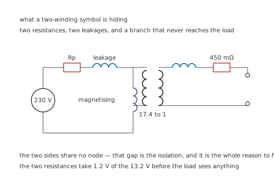
The two sides share no node — that gap is the isolation, and it is the whole reason to fit one.
The two-winding symbol on a schematic hides six components. Two of them explain the regulation.
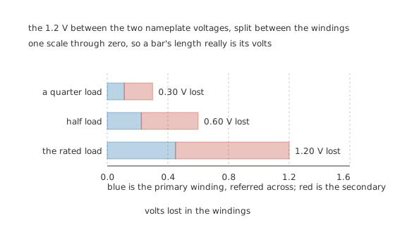
One scale through zero, so a bar's length really is its volts.
Worked example — Splitting the missing 1.2 volts
The secondary winding measures 450 mΩ, so at 1.67 A it takes 750 mV.
The primary winding, referred across to the secondary side, comes to 270 mΩ, so it takes 450 mV.
Those add to 1.2 V, which is exactly the gap between the two nameplate voltages. The regulation is not a separate property of the transformer; it is the winding resistance, restated.
Worked example — Adding up the losses
The same two resistances turn that current into heat: 1.25 W in the secondary and 750 mW in the primary, 2.0 W together.
The core costs an illustrative 1.4 W whatever the load, because it is being magnetised and demagnetised fifty times a second whether anything is connected or not.
Delivering 20 VA while losing 2.0 W and 1.4 W makes it 85.5 % efficient at its rating. Small transformers are not efficient devices, and this one is respectable for its size.
The leakage inductances in that circuit are the other half of the regulation, and they are why the number is worse on AC than the resistances alone predict. Flux that links one winding without linking the other behaves as a series inductance, and at fifty hertz it adds a reactive drop that is out of phase with the resistive one. On a small transformer the resistances dominate and the arithmetic above is close enough; on a large one, or on a part deliberately built with high leakage to limit its own short-circuit current, the reactive term takes over. Manufacturers publish regulation as a measured percentage rather than a calculation for exactly that reason.
The magnetising branch is the one that never reaches the load. It carries the current needed to push the flux round the core, it is there whether or not anything is connected to the secondary, and it is where the core loss lives. On a modest part it is a few per cent of the rated primary current, and it is the reason an unloaded transformer still draws something from the supply.
The two kinds of loss behave completely differently with load, and that difference is what the rating is built on.
Professional
What the rating is protecting, and what it is not
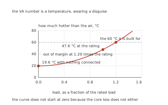
The curve does not start at zero because the core loss does not either.
Worked example — Reading the rating as a temperature
Against an illustrative 14 °C per watt to the air, the 1.4 W of core loss alone puts the transformer 19.6 °C above the room with nothing plugged into it.
At the rated load the copper adds its 2.0 W and the rise becomes 47.6 °C.
Take the declared 60 °C as the limit and there is margin for 1.20 times the rated load — and no more. The core loss is a floor the copper is stacked on top of, which is why a transformer's overload margin is smaller than the square law alone suggests.
That thermal picture also explains three things people find surprising.
A transformer with nothing connected is warm and costs money. The core loss is there permanently. An appliance left plugged in with its transformer energised burns its no-load loss continuously, which is where "vampire" standby consumption used to come from before switched-mode supplies took over.
Airflow is part of the rating. The same part in an enclosure, or lying flat where it was rated upright, runs hotter at the same load. The rating assumed a thermal resistance and the enclosure changed it.
The rating is not derated for duty cycle by any simple rule. A transformer has enough thermal mass to carry a substantial overload briefly, and no datasheet tells you how much. This is the one place where the manufacturer's own curves are worth more than any calculation.
The first cycles, which nothing on the label mentions
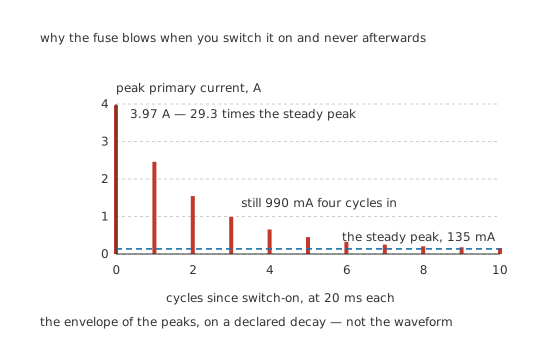
The envelope of the peaks, on a declared decay — not the waveform.
Worked example — Why the fuse blows on switch-on
Switch on at the wrong moment in the cycle — near a voltage zero crossing, with the core's remanent flux pointing the wrong way — and the flux has to swing to about twice its normal peak. The core saturates and its inductance leaves.
What is left in the way is the primary winding's own resistance, 82.0 Ω here, against a supply peak of 325 V. That is 3.97 A, against a steady peak of 135 mA — a factor of 29.3.
On a supply of 50 Hz, each cycle lasts 20 ms, and on a declared decay constant of 40 ms the peak is still 990 mA three cycles in. A fuse chosen for the running current is therefore carrying several times its rating for the best part of a tenth of a second. That is a fuse-type decision, not a fuse-rating one.
Toroidal parts have the worst of this and the best of everything else. A closed, gapless core has the lowest reluctance, so it magnetises with the least current, leaks the least field and runs the coolest for its size — and saturates hardest on switch-on for the same reason. Large toroidal supplies often need a soft-start circuit that a laminated part of the same rating would not.
Choose against three numbers, not one. The VA rating, the regulation at the load you will really draw, and the inrush the upstream protection has to tolerate. A transformer that satisfies the first and fails the second gives a supply that sags; one that fails the third gives equipment that trips its own breaker every time it is switched on.
Common mistakes
- Designing against the labelled secondary voltage — this one reads 13.2 V unloaded and 12.0 V loaded, and everything downstream sees both at different times.
- Reading the VA rating as an electrical limit — it is a thermal one. At the rating this part runs 47.6 °C above the air, and the margin to the declared 60 °C limit is only 1.20 times the rated load.
- Forgetting the no-load loss — 1.4 W of core loss is drawn permanently and puts the transformer 19.6 °C above the room with nothing connected.
- Sizing the fuse for the running current — the first peak here is 3.97 A against a steady peak of 135 mA, 29.3 times as much, and it is still 990 mA three cycles later.
- Treating regulation as a separate specification — it is the two winding resistances. 450 mΩ secondary and 270 mΩ referred primary at 1.67 A give exactly the 1.2 V the nameplate implies.
- Assuming the isolation is a property of the symbol — it is a property of the construction, and only a part built and approved for mains isolation has it.
Frequently asked questions
Why does my transformer read a higher voltage than the label says?
Because the label's voltage is quoted at the rated load, and a meter draws almost nothing. This one reads 13.2 V open and 12.0 V at its rated 1.67 A. The 1.2 V difference is the two winding resistances, and it is a regulation of 10 %.
What is the VA rating really limiting?
Temperature. At the rated load this part dissipates 2.0 W in copper and 1.4 W in the core, which against 14 °C per watt to the air is a 47.6 °C rise. The rating is the load that produces the rise the insulation was designed for, in the airflow the manufacturer assumed.
Why is a transformer warm when nothing is plugged into the secondary?
Because the core is being magnetised and demagnetised fifty times a second regardless. That costs 1.4 W here, which alone puts the part 19.6 °C above the room. Copper loss is what the load adds on top.
Why does the fuse blow when I switch it on?
Because the core can saturate in the first cycle, leaving only the primary winding's own 82.0 Ω against a 325 V supply peak. That is 3.97 A where the steady peak is 135 mA, 29.3 times as much, and it is still 990 mA three cycles later. The fix is a fuse type that tolerates a surge, not a larger fuse.
Are toroidal transformers better?
For efficiency, size, weight and stray field, generally yes: the closed core has the lowest reluctance. For inrush they are worse, for exactly the same reason, and a large toroidal supply often needs a soft-start circuit that a laminated part of the same rating would not.