
Quick Answer
Power factor is the ratio of the real power a load consumes to the apparent power its supply has to deliver, and for a sinusoidal load it equals the cosine of the angle between the voltage and the current. Correction fits capacitance beside an inductive load so the line stops carrying that load's reactive current.
Intuition
The part of the current that does no work
Someone pushing a loaded trolley across a warehouse floor rarely pushes straight along the direction of travel. The handle is at an angle, and only the component of the push lined up with the movement gets the trolley anywhere. The sideways component is genuine effort. It tires the arms and moves nothing.
An alternating supply feeding a motor sits in the same position. Current flows, the cable warms on all of it, and only part of that current is lined up with the voltage. The rest travels out to the magnetic field in the windings and comes back a fraction of a cycle later, over and over, without turning the shaft.
Power factor is the fraction that is lined up. A motor taking 8.0 A from a 230 V supply at a power factor of 0.70 puts 1840 VA through the wiring while converting 1288 W. Both figures describe the same machine on the same day.
The angle at which a motor wants its current is not negotiable; it comes from the physics of the windings. What can be changed is where the sideways current comes from. A capacitor across the motor's terminals wants its own current on the other side of the voltage, so the two components trade it between themselves and the supply cable is left out of the arrangement. Fit the right one and the same motor draws 5.89 A from the line while the shaft carries on as before.
Practitioner
Sizing the capacitor
Correction is arithmetic on a right triangle whose horizontal side cannot move: a capacitor changes nothing about the energy the motor converts, so the real power stays put while the other two sides shrink.
Sizing starts from two meter readings. RMS volts times RMS amperes gives the apparent power the supply must deliver.
A nameplate power factor scales that product down to the part the load consumes.
The third side is the reactive power, quoted in volt-amperes reactive and written var. It is not the plain difference between the first two, since they meet at a right angle; AC power works through why.
Worked example — An uncorrected motor, as the supply sees it
The motor takes 8.0 A from a 230 V supply, and its nameplate gives a power factor of 0.70.
The cable and the protective device ahead of it carry 1840 VA.
Of that, 1288 W reaches the shaft and the windings, and that is the figure the energy meter counts.
The vertical side comes to 1314 var, travelling out to the magnetic field and back every cycle.
A target power factor fixes the triangle correction has to produce: the base is known, so the new hypotenuse and vertical side follow from the target alone. The capacitor supplies the gap between the two reactive figures, and the supply voltage and frequency turn it into a capacitance.
Worked example — Correcting the same motor to a target of 0.95
Hold the real power at 1288 W and set the target at 0.95. The corrected apparent power comes out at 1356 VA, leaving 423 var on the vertical side.
The capacitor's share is the gap between the two reactive figures, 891 var.
On a 230 V supply at 50 Hz, that calls for 53.6 µF.
Line current falls from 8.0 A to 5.89 A, which is 26.3 % less copper loading for the same work done.
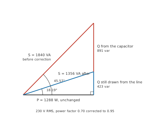
The two triangles share their base and differ in nothing else. Shorten the vertical side and the hypotenuse shortens with it, and the hypotenuse is what the cable carries.
Stock values are what get fitted, so the calculated figure is rounded to something a supplier holds; rounding down is the safer direction. The part is a mains-rated film capacitor whose voltage rating clears the peak of the supply, not its RMS value, and correction-duty units carry a reactive rating in kvar beside the microfarads.
Safety
The capacitor sized above is a mains-voltage part that goes on living after the contactor opens. Charged to the peak of the supply it holds 325 V, and opening a switch removes none of it.
A discharge resistor brings it down over a time set by the resistor multiplied by the capacitance. A 220 kΩ bleeder gives 11.8 s, so 120 V is still on the terminals one time constant after isolation, and only after 60 s is the residue down to 2.0 V. A standard sets the residual voltage such a capacitor must reach within a stated time, but a bleeder can be missing or open circuit. Prove the terminals dead with a meter, and discharge through a resistor, never a screwdriver.
Correction carries hazards beyond the stored charge. Capacitance on a supply that already carries harmonic current can resonate with it, as Layer 4 works through, and a capacitor left across a coasting motor keeps the windings excited, so the terminals stay live after the supply has gone.
Fitting correction to a mains installation is licensed work in most jurisdictions; the isolation sequence is in electrical safety, and capacitor charging and discharging covers the behaviour above.
A clamp meter on the supply lead confirms the result. Switch the capacitor in and the current drops while a wattmeter on the same circuit stays put.
Engineer
Cancelling var with var
The power factor and the phase angle are the same statement in two notations. For a sinusoidal voltage driving a sinusoidal current, the factor is the cosine of the angle between them, so a load quoted at a poor figure is one whose current arrives a long way behind its voltage. Take the arccosine of the power factor and the angle appears; feed that angle to a sine and the apparent power resolves into its reactive part, which is the second route to the same var figure the square root gave.
Why a capacitor cancels an inductor's demand comes down to the sign of that angle. An inductive load takes its current a quarter cycle after the voltage. A capacitor takes its current a quarter cycle before. Put the two side by side on the same terminals and their reactive currents are in antiphase, so at every instant one is absorbing what the other is returning. Nothing is consumed in the exchange, and the supply upstream sees only what is left over.
That gives a second way to size the part, working in ohms instead of var. The capacitor's reactance at the supply frequency sets how much current it draws at the supply voltage.
Worked example — The same correction checked through the capacitor's own current
The power factor of 0.70 is the cosine of 45.57°, and the target of 0.95 is the cosine of 18.19°.
Apparent power multiplied by the sine of the first angle gives 1314 var, matching the figure the square-root route returned.
At 50 Hz the capacitance of 53.6 µF has a reactance of 59.4 Ω, so the supply voltage drives 3.87 A through it.
Volts times amperes on the capacitor alone is 891 VA, and since an ideal capacitor consumes none of it, all of it is the reactive supply the motor wanted.
Rearrange that chain and the correction formula falls out of it: the reactive power a capacitor supplies is its voltage squared divided by its reactance, and reactance is the reciprocal of angular frequency times capacitance, so capacitance is reactive power divided by angular frequency times voltage squared. The library entry above is that expression with the angular frequency written out as two pi f.
The chain above rests on conditions nobody bothers to write down, and each of them is easy to break.
The voltage and the current are sinusoids at one frequency. Multiply components at different frequencies together and the product averages to nothing over a cycle, so a distorted current has no single angle to take a cosine of. What is then quoted as the power factor is still watts divided by volt-amperes, but it is no longer the cosine of anything, and the two figures are given separate names: the displacement factor for the angle of the fundamental, and the true power factor for the ratio of the two powers. Harmonics is where that split is worked through.
It also assumes the supply voltage holds still. Capacitance is sized from the square of it, so a supply running high delivers more correction than the calculation asked for and a supply running low delivers less.
The load is steady. A motor's reactive demand changes far less with mechanical loading than its real demand does, which means the power factor of a lightly loaded motor is worse than its nameplate, and a capacitor sized at full load over-corrects when the machine is idling.
And the cancellation happens only where the capacitor is. It keeps reactive current out of the conductors between itself and the source, so a unit at the switchboard does nothing for the cable running from the switchboard to the motor.
Professional
What a capacitor bank does to the supply behind it
Where the capacitance sits decides how much of the installation benefits. Mounted at the motor's terminals it unloads every conductor upstream, and it switches with the motor so it can never be left connected to a machine that has stopped; motor run and start capacitors are the same family of part. Mounted as a bank at a distribution board it serves a group of loads with fewer and larger units, and everything between the board and each motor still carries the full reactive current. At the incomer it satisfies the meter and nothing else. Cost falls and coverage falls together, and most installations end up with a mixture.
Anything larger than a single fixed unit is switched in stages by contactors under the control of a relay measuring the incoming power factor. Closing a contactor onto a discharged capacitor produces an inrush limited only by the circuit's stray inductance, so capacitor-duty contactors use pre-charging contacts or series damping inductors. A stage that has just been switched out is still charged, so the relay has to hold it off until its discharge resistors have done their work before it can be switched back in.
Over-correction is the failure mode of a bank that has been sized optimistically or left in a fixed configuration. Pushing past unity puts the current ahead of the voltage instead of behind it, and the supply carries just as much of it as it did lagging. It also lifts the voltage at the point of connection, because a leading current through the supply's own reactance adds to the voltage instead of subtracting from it. Sizing for a target below unity keeps a bank clear of that boundary at every load it will see.
The resonance risk is the one that catches people out, because it does not announce itself until a harmonic source arrives. A capacitor bank and the inductance of the supply ahead of it form a parallel resonant circuit, and resonance at that frequency turns the pair into a high impedance seen from the load. Harmonic current injected at or near that frequency then develops a much larger voltage than it otherwise would, and circulates between the bank and the supply at an amplitude neither was sized for. Where it lands is set by the two components between them.
Worked example — Where the bank and the supply resonate
Take a supply inductance of 1.5 mH, a figure chosen to make the arithmetic visible and not read off a transformer's data sheet.
With 53.6 µF across it the pair resonate at 3527 rad/s, or 561 Hz.
Divided by the supply frequency of 50 Hz, that lands at harmonic number 11.2, close enough to the eleventh to matter on a supply feeding rectifiers.
The remedy is a detuned bank: a small inductor in series with each capacitor stage, chosen to put the combination's resonance below the lowest harmonic present, usually somewhere under the fifth. The stage still supplies var at the supply frequency and presents an inductive impedance above the tuning point, so the magnification never happens. Where harmonic current has to be removed instead of avoided, the same components are proportioned as a tuned filter. Limits on what an installation may inject at the point of common coupling are set by the standard that applies in the jurisdiction, and the harmonic survey that establishes compliance is normally what tells a designer whether detuning is needed at all.
Electronic loads change the problem instead of adding to it. A rectifier feeding a reservoir capacitor draws its current in short bursts near the peaks of the waveform, and the fundamental component of those bursts can sit almost in step with the voltage. Displacement is close to one while the true power factor stays poor, so a correction capacitor has nothing useful to cancel and simply offers the harmonics a low impedance path. The fix there is active power factor correction inside the equipment, a switching stage that draws a sinusoidal current in phase with the supply, and it is a mandatory feature above a certain input power in several markets.
The instrument matters as much as the reading. Meters differ in whether they display the displacement factor or the ratio of watts to volt-amperes, and on a rectifier load the two disagree badly. Tariffs vary too: household metering counts kilowatt-hours and sees the real power alone, while larger consumers are commonly billed on peak demand in kilovolt-amperes or carry a charge attached to a poor power factor, with the terms set by the supply contract. Correction pays for itself out of that charge and out of the reduced losses in everything upstream, all the way back through the distribution network, where the same reasoning holds at a scale of megavars.
Common mistakes
- Reading power factor as an efficiency — it describes the angle of the current, not what happens to the energy that does arrive. An inefficient motor can have an excellent power factor, and a good one can have a poor factor at light load.
- Sizing the capacitor from the load's wattage — correction is sized in var, which needs the angle as well as the power. Watts alone say nothing about how much reactive current is flowing.
- Fitting a plain capacitor to a load that draws a distorted current — displacement is not what is wrong there, and the capacitor gives the harmonics a low-impedance path into itself. Establish what the current looks like before choosing a remedy.
- Rating the capacitor on the RMS supply voltage — the dielectric sees the peak, and it sees switching transients on top of the peak. Rate it above both.
- Correcting to unity and leaving a fixed bank connected — reactive demand falls as a motor unloads, so a bank sized at full load pushes the current leading at light load and raises the terminal voltage.
- Treating an opened contactor as a discharged bank — correction capacitors hold their charge, and a multi-stage bank holds a great deal of it. Prove each stage dead before touching any of it.
Frequently asked questions
Will correcting the power factor reduce my electricity bill?
On a household meter, no. That meter counts kilowatt-hours and correction does not change the kilowatts. Larger installations are a different matter, since many tariffs add a charge for a poor power factor or bill on peak demand in kilovolt-amperes, and correction is aimed squarely at that term.
Can the power factor be greater than one?
No. It is the ratio of real power to apparent power, and the real power is the average of a product whose amplitude is the apparent power. A calculation that returns more than one has an error in it, most often a peak value used where an RMS value belongs.
Why not correct all the way to unity?
A load's reactive demand moves with its mechanical loading, so a capacitor sized for unity at full load over-corrects at every other operating point. Leading current is no easier for the supply to carry than lagging current, and it lifts the local voltage as well.
What does the kvar rating on a correction capacitor mean?
The reactive power it supplies at its rated voltage and frequency. It restates the capacitance in the units the sizing calculation works in, and it changes with the square of the applied voltage, so the same unit on a lower supply delivers appreciably less than its label.
Does a capacitor correct the power factor of a switching power supply?
Not usefully. The poor figure there comes from the shape of the current, which is drawn in bursts near the peaks of the waveform, and a capacitor can only shift an angle. Correction for that kind of load is a switching stage built into the equipment.