
Quick Answer
A capacitor charges and discharges along an exponential curve, quickly at first and then ever more slowly as the driving voltage difference shrinks. The resistance in the path sets the current, and with the capacitance it sets how long the whole process takes. The charge remains after the supply is removed.
Intuition
The light that stays on after you pull the plug
Switch off a piece of equipment and watch the indicator LED. On plenty of things it does not go out at once; it fades over a second or two, sometimes longer. Nothing is powering it. What is keeping it alight is a capacitor inside that was charged up while the equipment was running and is now emptying itself through whatever is still connected.
That fade is the shape of every charge and discharge there is. It starts fast and finishes slowly, and it never quite finishes at all. The reason is worth getting straight at the outset, because everything else follows from it. Current flows onto a capacitor only when there is a voltage difference to push it, and as the capacitor fills, that difference shrinks. Less push means less current, less current means slower filling, and slower filling means the difference shrinks more slowly too. The process talks itself down.
Discharge is the same story played backwards. A full capacitor connected to a resistor drives a large current at first, because its voltage is high. As it empties, its voltage falls, so the current falls with it, so the emptying slows. The last few per cent take as long as the first sixty did.
A capacitor's voltage cannot jump — it can only travel along that curve, however hard you push. And a capacitor that has been charged stays charged when the power goes away, sometimes for a very long time. That second fact is a convenience in a memory circuit and a genuine hazard in a power supply.
Practitioner
The curve, in numbers
Connect a supply to a capacitor through a resistor and three quantities set everything: the supply voltage, the resistance, and the capacitance. The resistance and the capacitance combine into a single time-scale:
and the voltage on the capacitor follows an exponential approach to the supply:
Worked example — Charging a 4.7 µF capacitor through 22 kΩ
With 22 kΩ in the charging path and 4.7 µF on the end of it, the time-scale works out at 103.4 ms.
At the instant of switch-on the capacitor is still at zero, so the whole of the 9.0 V supply appears across the resistor, and the current is at its largest: 409 µA. That is the peak the source has to be able to deliver.
One time constant later the capacitor has reached 5.69 V. After three it is at 8.55 V, and closing on the supply about as slowly as it is possible to close on anything.
Discharge follows the mirror-image law, a decay towards zero rather than an approach to the supply:
Worked example — And letting it go again
Disconnect the supply and let the same capacitor empty through the same resistor. After two time constants it still holds 1.22 V, roughly a seventh of where it started.
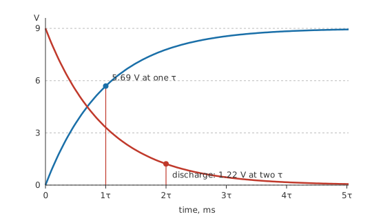
The percentages along the curve are fixed. They do not depend on the supply voltage, the resistance or the capacitance — only on how many time constants have gone by — and the RC time constant lesson tabulates them and shows where they come from. The practical convention is that five time constants counts as finished, at a bit over 99 %.
The resistance that matters on the bench is everything in the charging path, which includes the source's own output impedance and the wiring, not only the resistor you fitted. The capacitor's voltage is the trace to watch on a scope: feed the network a square wave, and the shape of the rising edge gives the time constant directly.
Engineer
What the current is doing while the voltage moves
The voltage curve gets all the attention, and the current curve is the one that explains the circuit. Current into a capacitor is proportional to how fast its voltage is changing:
At switch-on the voltage is climbing steeply, so the current is large. As the curve flattens, the current dies away with exactly the same exponential shape, reaching zero at the same rate the voltage reaches the supply. Current and voltage are therefore in a fixed relationship throughout: their sum, weighted by R and C, always reconstructs the supply, which is Kirchhoff's voltage law applied round the loop at every instant.
Charging through a resistor is only one way to do it. Charge from a current source instead and the picture changes completely, because a constant current means a constant rate of voltage change, which is a straight line rather than a curve:
Worked example — The same capacitor, driven by a current source
Feed 100 µA into 4.7 µF and hold it constant. The voltage climbs in a straight ramp, and reaching 9.0 V takes 423 ms.
There is no exponential anywhere. The curve exists only because a resistor's current depends on the voltage across it, and that voltage is the very thing that is changing. Remove that dependence and the capacitor integrates the current directly.
This is why current-source charging is used wherever a linear voltage ramp is needed — sawtooth generators, dual-slope converters, the timing stages of some oscillators — and why an RC integrator only approximates a true integrator over the part of the curve that is still nearly straight.
Where does the energy go? Charging a capacitor through a resistor wastes exactly as much energy in the resistor as it stores in the capacitor, regardless of the resistance chosen. Make the resistor smaller and the charging is faster but the current is proportionally larger, and the two effects cancel exactly. That result surprises people, and it is the reason a switching converter uses an inductor rather than a resistor to move charge about. The energy stored in a capacitor lesson does the accounting.
The ideal model has limits, and they show up at both ends of the curve. At the very start, the capacitor's equivalent series resistance adds a small instantaneous step before the exponential begins, since a real capacitor is a capacitance with a resistance in series with it. At the very end, leakage means the capacitor never reaches the supply exactly, and its own self-discharge sets a floor on how completely it can hold what it has. Neither matters in a timing circuit at audio speeds; both matter in a sample-and-hold or a nanosecond-scale pulse.
Professional
What still holds charge after the power is off
A capacitor that has been charged is a stored-energy component, and in a mains-derived supply that is not a figure of speech.
Worked example — A supply reservoir, and what a bleeder resistor is for
Take a reservoir capacitor of 470 µF charged to 400 V, with a bleeder resistor of 100 kΩ fitted across it to drain it after power-off.
That pair has a time constant of 47.0 s. One time constant after the supply is removed, the capacitor is still sitting at 147 V — nothing like safe.
Waiting five time constants, 235 s, brings it down to a few volts. Nearly four minutes, on a design that has a bleeder fitted and working.
That calculation is what the discharge time warnings on equipment covers are quoting. Without a bleeder, the only discharge path is the capacitor's own leakage and whatever the surrounding circuit happens to present, and the time can stretch from minutes into hours.
Sizing the bleeder is a straight trade. Too large a resistance and the capacitor takes an unsafe age to drain; too small and it wastes power continuously while the equipment runs. Safety standards for particular equipment classes specify a maximum discharge time and the value follows from that, which is a rule to look up for the standard that applies rather than to guess.
Repeated charge and discharge is a duty cycle, and it wears the part. Each cycle pushes ripple current through the ESR, which heats the capacitor from the inside, and heat is the dominant ageing mechanism in electrolytics. A capacitor chosen only on capacitance and voltage rating, and then asked to cycle hard, fails early for reasons that never appear in the circuit simulation.
Where the discharge is deliberately fast, the resistance in the path is often smaller than anything you fitted. A photographic flash tube, a capacitor discharge welder or a crowbar circuit dumps a large capacitance through milliohms, and the peak current is limited by ESR and loop inductance rather than by any resistor. That regime damages switches, vaporises thin traces and is not something to arrange casually.
At the opposite extreme, holding a voltage rather than moving it is its own design problem. A sample-and-hold capacitor loses charge through its own leakage, through the switch's off-state leakage and through the amplifier's input current, and the dielectric it is made of decides how much of the rest it gives back. Polypropylene and C0G are the materials that behave; electrolytics and Class 2 ceramics are not in the conversation.
Safety
Capacitors are the first components in this course that stay dangerous with the power off. Before working inside any mains-derived supply, an amplifier, a camera flash or a motor drive: isolate it, wait out the stated discharge time, and then measure the reservoir with a meter to confirm it has actually drained — a failed bleeder resistor gives no warning that it has failed. Never short a large capacitor with a screwdriver or a lead; the peak current can weld metal and throw molten copper, and the shock loading damages the part. Use a purpose-made discharge tool, or a suitably rated resistor on insulated leads, and check with the meter afterwards. The 400 V figure above is arithmetic on a paper example, not something to reproduce on a bench, and everything in electrical safety fundamentals applies before any of this does.
Common mistakes
- Expecting a capacitor to be "fully charged" at some moment — the approach is asymptotic. Five time constants is a convention at a bit over 99 %, not a finish line.
- Counting only the resistor you fitted — the source's output impedance and the wiring are in the charging path too, and dominate it when the fitted resistor is small.
- Assuming a switched-off circuit is a safe circuit — a reservoir capacitor can hold a lethal voltage for minutes, and for far longer if its bleeder has failed.
- Shorting a charged capacitor to discharge it — the peak current is limited only by ESR and loop inductance, and it damages both the part and whatever you shorted it with.
- Expecting a straight ramp from a resistor — a resistor's current falls as the capacitor fills, so the result is exponential. A straight ramp needs a current source.
- Choosing a capacitor for a hard cycling job on value and voltage alone — the ripple current flows through the ESR and heats the part from inside.
Frequently asked questions
Why does a capacitor charge along a curve rather than a straight line?
Because the current depends on the voltage across the resistor, and that voltage is the difference between the supply and the capacitor. As the capacitor fills, the difference shrinks, so the current falls and the filling slows.
How long does a capacitor take to charge?
Five time constants brings it to a bit over 99 % of the supply, which is the usual working answer. Strictly it never gets all the way there, so precision circuits state a threshold instead.
What limits the initial charging current?
The resistance in the charging path, since at the first instant the capacitor is still at zero volts and the whole supply appears across that resistance. If the only resistance is the wiring, the peak current can be very large.
How do I get a linear voltage ramp instead of a curve?
Charge from a current source. A constant current means a constant rate of change of voltage, so the ramp is straight for as long as the source can hold its current.
Is a switched-off circuit safe to touch?
Not on its own. Reservoir capacitors hold their charge after the supply is removed, and a bleeder resistor takes time to drain them. Isolate, wait the stated time, then measure to confirm.