
Quick Answer
A passive RC integrator takes its output across the capacitor and produces a running sum of the input, provided the time constant is long compared with the input's timescale. Swapping the output to the resistor gives a differentiator, which responds to how fast the input is changing instead.
Intuition
Two circuits from the same two parts
A resistor and a capacitor in series across a signal is about the simplest arrangement in electronics, and it does two completely different jobs depending on which component you take the output from.
Take the output across the capacitor, and you get something that accumulates. Feed in a square wave and the output is not a square wave; it is a set of ramps, rising while the input is high and falling while it is low, because the capacitor is filling and emptying. Sharp changes at the input are smoothed away, and what comes out is a running total of what went in. That is an integrator.
Move the output to the resistor instead, and you get the opposite. Current only flows through the resistor while the capacitor's voltage is changing, so the output responds to change rather than to level. A square-wave input produces a spike at every edge and nothing in between, because the edges are the only moments when anything is changing. That is a differentiator.
Neither is doing real mathematics. They are approximations, and they only behave the way their names suggest if the time constant is chosen correctly for the signal. A time constant that is too short turns an integrator back into something that just follows its input; one that is too long turns a differentiator into a wire. Choosing that time constant is most of the design work, and the rest of this lesson is about how.
Practitioner
Getting the time constant right
Both circuits share the same time constant, and it is the only thing you get to choose:
For an integrator the time constant must be long compared with the input's shortest features, so that the capacitor never gets anywhere near fully charged and stays on the early, nearly straight part of its curve:
Worked example — An integrator, and how straight the ramp really is
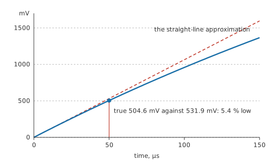
Take 47 kΩ and 10 nF, giving 470 µs, and feed it a square wave of 5.0 V whose half-period is 50 µs.
The true capacitor voltage at the end of the half-period is 504.6 mV, from the exponential charging law:
By the straight-ramp approximation an integrator is supposed to deliver, it would have been 531.9 mV.
The two differ by 5.4 %, which is the price of the approximation at this ratio. Make the time constant longer and the error falls; make it shorter and the ramp starts visibly curving.
For a differentiator the requirement reverses: the time constant must be short compared with the input's features, so the capacitor finishes charging long before the input changes again and the resistor voltage has time to fall back to zero between edges.
Worked example — A differentiator, and how fast the spike dies
Take 1.0 kΩ and 1.0 nF, giving 1.0 µs.
A rising edge of 5.0 V appears across the resistor immediately, because the capacitor cannot change its voltage instantly. The spike then decays, and 2.0 µs later it is down to 676.7 mV.
The useful rule of thumb is a factor of ten in either direction: a time constant ten times the pulse width for a usable integrator, a tenth of it for a usable differentiator. Between those, the circuit is neither, and it is simply an RC network with an exponential response — which is often exactly what is wanted, and is what pulse response and rise time is about.
A practical warning that follows from the arithmetic: a passive integrator's output is small. The better the integration, the less of the input appears at the output, since a long time constant means the capacitor barely charges. There is no way round that in a passive circuit, and it is the main reason serious integration uses an op-amp rather than two components.
Engineer
Why the approximations work, and where they stop
Start from the current into the capacitor, which is proportional to how fast its voltage changes:
In the integrator, suppose the output voltage across the capacitor stays small compared with the input. Then essentially the whole input voltage appears across the resistor, so the current is the input voltage divided by R — independent of the output. A current proportional to the input, charging a capacitor, produces a capacitor voltage proportional to the accumulated input over time. That is integration, and the constant of proportionality is one over RC.
Every word of that argument depends on the output staying small. As the capacitor charges, less of the input is left across the resistor, the current falls, and the accumulation slows — which is the exponential curve reasserting itself.
Worked example — How far from ideal the Layer 2 integrator sits
The time constant of 470 µs is 9.4 times the half-period of 50 µs.
That ratio is what bought the 5.4 % error. Doubling it roughly halves the error, and there is no threshold at which the circuit becomes a true integrator — only a ratio at which the error is small enough for the job.
The differentiator's argument is the mirror image. If the resistor voltage stays small compared with the input, then essentially the whole input appears across the capacitor, the current is C times the rate of change of the input, and the resistor turns that current into a voltage proportional to that rate of change. Again the approximation holds only while the output is small.
Both circuits have a second identity that is worth recognising, because it is the same circuit seen from the frequency domain rather than the time domain. An RC integrator is exactly a low-pass filter, and an RC differentiator is exactly a high-pass filter — same components, same time constant, different question asked of it. "Integrates the signal" and "attenuates the high frequencies" are two descriptions of one behaviour, and the cutoff frequency is where the time constant reappears as a frequency.
The stated limits, then, are these. Neither circuit integrates or differentiates exactly; both are first-order responses that approximate those operations over a limited range of input timescales. The approximation error grows as the output grows, so accuracy and output amplitude trade against each other directly. And neither has any gain — passive networks cannot amplify — so an integrator good enough to be accurate delivers an output that may need amplifying afterwards, by which point an active integrator would have been simpler.
Professional
What loading and reality do to both circuits
A passive RC network has no output buffer, so whatever it drives becomes part of it.
Worked example — An integrator with something connected to its output
Put a load of 100 kΩ across the capacitor of the Layer 2 integrator.
At DC the capacitor is out of the picture and the circuit is a plain divider between 47 kΩ and that load. A steady 5.0 V input settles at 3.40 V rather than at the input voltage.
The load has also shortened the effective time constant, because the capacitor now discharges through the load resistance as well as charging through R. A high-impedance buffer removes both problems at once.
Source impedance does the same thing from the other end. The R in the time constant is everything in the charging path, so a signal source with a significant output impedance adds to it, and a differentiator fed from a source that cannot supply the edge current will not produce the spike the arithmetic promised.
The differentiator has a failure mode all its own: it amplifies noise. Its output is proportional to the rate of change of the input, and noise is the fastest-changing thing in most signals, so a differentiator faithfully picks out exactly what you did not want. The standard mitigation is a small resistor in series with the capacitor, which flattens the response above some frequency and puts a ceiling on the gain — turning an ideal differentiator into a band-limited one, which is what every practical differentiator actually is.
The integrator's characteristic failure is drift. Any DC offset at the input is integrated too, and integrating a constant gives a ramp that grows without limit until something saturates. In the passive circuit the resistor path prevents this by leaking the offset away, which is the same thing as saying the passive integrator is not a true integrator; in an active one it has to be prevented deliberately, with a resistor across the feedback capacitor.
Both circuits appear far more often than their names do. Every RC snubber, every supply decoupling network and every deliberate slew-limiting resistor on a gate drive is an integrator by another name. Every AC-coupling capacitor at the input of an amplifier is a differentiator, and the "droop" seen on a long pulse through a coupling capacitor is exactly the differentiator's decay. Recognising the topology is more useful than remembering the labels.
Component choice matters in the same way it does anywhere the value sets a timescale. The dielectric decides how much the time constant moves with temperature and applied voltage, and dielectric absorption in a Class 2 ceramic quietly returns charge into an integrating node after every transition. Where the shape of the output matters rather than merely its presence, a film or C0G capacitor is the part to specify.
Common mistakes
- Assuming the circuit integrates whatever the time constant — integration needs a time constant long compared with the input's features, and a short one just gives back a slightly rounded copy of the input.
- Expecting useful output amplitude from a good passive integrator — accuracy and output level trade directly, since a long time constant means the capacitor barely charges.
- Loading the output without a buffer — whatever the network drives becomes part of it, changing both the DC level and the effective time constant.
- Building a differentiator with no high-frequency limit — it responds to the fastest thing present, which is usually noise. A small series resistor caps the gain.
- Forgetting the source impedance — the R in the time constant is everything in the charging path, not only the resistor you fitted.
- Using a Class 2 ceramic where the output shape matters — its value moves with temperature and bias, and dielectric absorption feeds charge back into the node.
Frequently asked questions
What is the difference between an RC integrator and a differentiator?
Only which component the output is taken from, and how the time constant compares with the signal. Across the capacitor with a long time constant gives an integrator; across the resistor with a short one gives a differentiator.
How do I choose the time constant?
A working rule is a factor of ten. For an integrator, make the time constant about ten times the shortest feature in the input; for a differentiator, about a tenth of it. Between those the circuit is neither.
Why is my passive integrator's output so small?
Because that is what good integration costs. A long time constant means the capacitor charges only a little during each input feature, so accuracy and output amplitude pull against each other. An active integrator breaks the trade by adding gain.
Is an RC integrator the same thing as a low-pass filter?
Yes — the same components with the same time constant, described in the time domain instead of the frequency domain. The differentiator is likewise a high-pass filter.
Why does my differentiator output so much noise?
Because it responds to rate of change, and noise changes faster than the signal. Adding a small resistor in series with the capacitor limits the high-frequency gain and makes the circuit usable.