
Quick Answer
The cutoff frequency of a filter is the frequency at which its output power has fallen to half of what it passes lower down. Half the power leaves roughly seven tenths of the amplitude, a drop of three decibels. In a single resistor and capacitor section it lands where the capacitor's reactance equals the resistance.
Intuition
The frequency a filter is named after
A filter does not switch anything off. Feed a low-pass section a slow signal and nearly all of it appears at the output; feed it a fast one and only a fraction survives. In between there is no cliff. The output sags, gently at first and then steadily, and somewhere along that sag a line has to be drawn so the whole curve can be described by one number.
That line is the cutoff frequency, and it is drawn where the output power has dropped to half. Power is what a signal delivers to whatever comes next, so halving it is a defensible place to say the filter has started doing its job.
Halving the power does not halve the voltage. Power grows with the square of the amplitude, so at that frequency the amplitude is still 0.707 of what it was down in the flat region, while the power is 0.500 of it. Written on the decibel scale the same drop comes out as -3.01 dB, which is how a filter's cutoff frequency and its "-3 dB point" turn out to be one place with two names.
Nothing physical happens there. The circuit has no idea the frequency is special; the number is a marker placed on a smooth curve so that two engineers can agree where a filter sits without swapping graphs. Both of the usual names, cutoff and corner, are a little optimistic about how abrupt the change is.
Practitioner
Putting a number on the corner
Only the product of the two parts matters. Ten times the resistance with a tenth of the capacitance gives the same corner, so the pair gets chosen on other grounds: what the source can drive, and which capacitance is available in a dielectric stable enough for the job. Capacitive reactance is the part of the circuit that changes as the signal speeds up. The resistor stays put while the capacitor's opposition falls away beneath it.
Which component the output is taken from decides which side of the corner survives, but not where the corner sits. A low-pass and a high-pass made from the same resistor and the same capacitor share one cutoff frequency; they simply keep opposite halves of the spectrum.
Worked example — A 2.2 kΩ resistor with a 47 nF capacitor
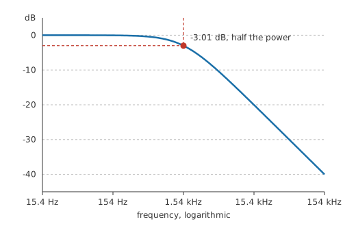
With 2.2 kΩ in series and 47 nF from the output to ground, the corner falls at 1.54 kHz.
Drive the input at that frequency with 2.0 V and 1.41 V comes out, the input scaled by 0.707. Quoted the usual way, the section is -3.01 dB at its own cutoff.
Placing a corner anywhere from a fraction of a hertz to several megahertz is easy enough on paper. The practical limits come from the components: a very low corner needs either a large resistance, which is noisy and easily loaded, or a large capacitance, which is bulky and rarely stable; a very high one eventually runs into the stray capacitance of the wiring and of whatever is measuring it.
Finding the corner on the bench takes a function generator and an oscilloscope. Start well below the expected cutoff, note the output amplitude, then sweep upward until the output has fallen to seven tenths of that reading. Watch the input on the second channel while sweeping, because a generator with real output resistance will not hold its amplitude into a load whose impedance is moving. The dial reading at that moment is the cutoff frequency. Sweeping until the output is half the input finds the -6 dB frequency instead, which is a different and considerably higher place on the curve.
Engineer
Reactance equal to resistance
A series resistor with a shunt capacitor is a voltage divider whose lower leg keeps changing value. The capacitor's reactance is large at low frequencies, so almost the whole input appears across it, and it shrinks as frequency rises, so the output shrinks with it. Between those two regimes there is one frequency at which the reactance and the resistance are equal, and that is the frequency the corner is defined at.
Setting the reactance expression equal to R and solving for frequency gives one over two pi R C directly. Nothing else enters the algebra, so the corner depends on the product and never on the individual values.
The two oppositions do not simply add. Current through a capacitor leads the voltage across it by a quarter cycle, so the resistor's drop and the capacitor's drop are a quarter cycle apart in phase and combine as the root of the sum of their squares. The gain magnitude is therefore one over the root of one plus the squared ratio of frequency to corner frequency, and the square root sitting in it is that quarter-cycle offset showing up in the arithmetic. At the corner the ratio is one, the denominator is the root of two, and the gain is its reciprocal.
Because R multiplied by C is also the RC time constant, the same circuit can be described from the time domain and the frequency domain with one number between them.
Worked example — The same section, read as a time constant
The resistor and capacitor above give 103.4 µs.
Divide one by two pi times that figure and the corner comes back as 1.54 kHz, matching the value found from R and C separately. A time constant and a cutoff frequency are the same fact about a circuit, stated in seconds or in hertz.
Turning a gain ratio into decibels needs the amplitude form, since a gain is a ratio of two voltages:
Worked example — A decade either side of the corner
A decade below, at 153.9 Hz, the gain is 0.995, or -0.043 dB. A loss that small is invisible on a scope and close to invisible on a meter.
A decade above, at 15.4 kHz, the gain has dropped to 0.0995, which is -20.04 dB. From there on, each additional decade costs another twenty decibels.
Those two figures set the shape of the whole response: level below the corner, falling at twenty decibels per decade above it, and bending through the middle over a couple of decades. Sketching a filter from its corner and its slope is the basis of the Bode plot.
Where the model stops is worth being clear about. It describes one pole, and a network with two reactive components has a different shape that can peak before it falls. It assumes a steady sinusoid, so it says nothing about the first few cycles after a step, which is the view the time-constant lesson takes of the same circuit. Linear, unchanging parts are taken for granted, and a capacitor whose value shifts with the voltage across it is neither. So is an unloaded output: any resistance placed across the capacitor joins the divider and moves the corner. The expression is also a magnitude alone. Phase runs from zero well below the corner to a quarter cycle of lag well above it, passing through half of that at the corner itself, so two filters can share a magnitude curve and still behave differently.
Professional
How far to trust the number
The corner printed on a schematic is a nominal figure, and several things move it before the board is powered.
Tolerance moves it first. Suppose the section above uses a resistor held to 1.0 % and a capacitor to 10 %, an illustrative pairing and not a quotation from any catalogue. Since the corner goes as one over the product, the two tolerances stack: the worst-case corner sits somewhere between 1.4 kHz and 1.7 kHz. Capacitor tolerance dominates, which is the usual case, and tightening the resistor buys almost nothing until the capacitor is tightened too. Where the corner has to stay put, the dielectric matters more than the tolerance line on the datasheet: class 2 ceramics lose a substantial fraction of their capacitance under DC bias and over temperature, so a corner set with one can drift well outside its stated tolerance in service. Class 1 ceramics and film parts hold their value.
Source and load move it next. The R in the expression is every resistance in the series path, not only the marked component.
Worked example — The same section behind a real source
Add a source with 600 Ω of output resistance and the series path becomes 2.8 kΩ.
The corner drops from its nominal figure to 1.21 kHz, with neither marked component altered.
The same argument runs at the other end. Cable capacitance, a scope probe and the next stage's input capacitance all sit across the capacitor and add to it. Both effects push the corner down, and both are easy to leave out of a hand calculation.
A single corner is also a weak filter. Twenty decibels per decade means two decades of separation to reach forty decibels of rejection, which is often more separation than the signal allows. The answers are more poles, from a cascade of sections or an active design, or a resonant network that puts its rejection where it is needed. Cascading has a trap: two identical sections each three decibels down at their own corner are six decibels down together, so the pair's own -3 dB point lies below either section's, and unbuffered sections load one another as well.
Bandwidth is not always quoted at three decibels down, and the rival conventions in circulation catch people out.
The equivalent noise bandwidth of a single pole is pi over two times the corner frequency, which for this section is 2.42 kHz. It is the width of the ideal brick-wall filter that would pass the same noise power, and it lands above the corner because the slope keeps letting noise through past it.
The rise time of the same pole follows from its bandwidth:
For this section that comes to 227.4 µs, the ten to ninety per cent transition its output would show on a step input. Pulse response and rise time develops that link; the point here is that a bandwidth figure and an edge speed are two readings of one pole.
Instrument and component datasheets are not always explicit about which definition they used, and some specify a passband ripple limit or a settling requirement in place of a corner. Read the definition before comparing two parts on their bandwidth numbers.
One pole is where every more elaborate filter starts. A transfer function collects the poles of a network into one expression, band-pass and band-stop designs are built by combining corners, and an amplifier's quoted bandwidth is usually the corner of the single dominant pole its designers arranged deliberately.
Common mistakes
- Reading -3 dB as half the voltage — it is half the power, and the amplitude at that point is still about seven tenths of the passband value. Half the voltage is the -6 dB frequency, noticeably further out.
- Treating the corner as a boundary — a single RC still passes a good deal above its cutoff and already attenuates a little below it. Rejection comes from distance past the corner, or from more poles.
- Leaving the source resistance out of R — whatever drives the network sits in series with the resistor. Add it in before trusting the corner the two marked components suggest.
- Setting a coupling corner on amplitude alone — phase shift reaches much further from the corner than attenuation does, so a corner tucked just below the lowest wanted frequency can still rotate it.
- Trusting a class 2 ceramic to hold a corner — its capacitance moves with bias, temperature and age, and the cutoff follows.
- Expecting two cascaded sections to keep the corner — each is three decibels down at that frequency, so the pair is six decibels down there and its own cutoff has moved lower.
Frequently asked questions
Why is the cutoff defined at half power and not at half amplitude?
Power is the quantity that matters at the end of a signal chain, and half of it is a natural halfway mark. Half amplitude would be a legitimate definition too, and it exists as the -6 dB point, but it is further out on the curve and no more meaningful. The half-power choice also makes the number the same whether a system is described by voltages or by powers.
Is the -3 dB point exactly 3 dB?
No. The exact figure is a shade over three decibels, and the round number is a convenient shorthand that has stuck. The difference never matters in practice, but a measurement that lands a hundredth of a decibel away from three is not an error.
Do a low-pass and a high-pass from the same R and C share a cutoff?
Yes. The corner depends only on the product of the resistance and the capacitance, and both circuits contain the same two parts. Moving the output from the capacitor to the resistor swaps which side of that frequency is kept and leaves the frequency itself alone.
How do I convert a time constant into a cutoff frequency?
Divide one by two pi times the time constant. The two describe the same circuit, one in seconds and one in hertz, so a circuit specified by its step response can be compared directly with one specified by its bandwidth.
Does the cutoff frequency change with signal amplitude?
Not for a linear circuit. Resistance and capacitance set the corner, and neither depends on how large the signal is. Amplitude does start to matter once a part behaves non-linearly, which happens with some ceramic dielectrics under bias and with any stage driven into clipping.