
Quick Answer
A passive low-pass filter is a resistor in the signal path with a capacitor from the output down to ground. Frequencies below its cutoff reach the output nearly intact, and above the cutoff the output falls by twenty decibels for every tenfold rise in frequency. The corner sits at one over two pi R C.
Intuition
Letting the slow part through
Music from a room further along the corridor arrives as thump and mumble. The bass comes through the wall almost intact while the cymbals and the consonants do not, and nobody switched them off on the way. A wall carries low frequencies more easily than high ones. A low-pass filter does the same thing to an electrical signal, deliberately, with two components.
The circuit is a resistor sitting in the signal path and a capacitor running from the far side of that resistor down to ground. Whatever appears across the capacitor is the output. At low frequencies the capacitor conducts hardly at all, so almost nothing gets diverted through it and the output follows the input. Speed the signal up and the capacitor conducts more freely, sending a growing share of the signal to ground before it can reach the output.
Nothing snaps shut between those two behaviours. The output slides down a smooth slope, and the frequency at which the slide has gone far enough to be worth naming is the cutoff frequency. Below it the section is close to transparent. Well above it, each tenfold rise in frequency costs another factor of ten in amplitude, so a signal ten times too fast loses roughly nine tenths of itself, and one a hundred times too fast loses ninety-nine hundredths.
A gentle decline is what two components buy. Sharper edges take more parts, and they are paid for in ways the last layer of this lesson gets to.
Practitioner
Picking R and C for a corner
An RC low-pass section is a voltage divider whose lower arm shrinks as the signal speeds up. Read it that way and the shape of the response is available before any algebra: a huge lower arm keeps nearly all of the input, a tiny one keeps almost none of it, and the interesting frequencies are the ones in between.
The two values enter as a product, which leaves one of them free. Settle the resistor first, since it sits in series with whatever drives the filter and with whatever the filter feeds: small enough that the source can still hold its amplitude across it, large enough that the source is not being asked to drive a near short. Somewhere between a few hundred ohms and a few tens of kilohms suits most small-signal work. The capacitor then follows from the corner wanted, and gets rounded to a stocked value before anything else is decided.
Capacitive reactance is the part of the circuit that moves. The resistor holds still while the capacitor's opposition falls in inverse proportion to frequency.
Worked example — A 1.5 kΩ resistor with a 220 nF capacitor
With 1.5 kΩ in the signal path and 220 nF from the output down to ground, the corner lands at 482 Hz.
Evaluate the capacitor's reactance at that frequency and it comes back as 1.5 kΩ, matching the resistor. Equal opposition in the two arms is what the corner marks, and the output there is 0.707 of the input.
The gain magnitude at any frequency comes from the ratio of that frequency to the corner:
Filter responses are quoted on the decibel scale far more often than as a plain ratio, and a gain is a ratio of two voltages, so the amplitude form is the one to use:
Worked example — A decade either side of that corner
At the corner itself the section is -3.01 dB.
A decade below, at 48.2 Hz, the output is 0.995 of the input. That is a loss of -0.04 dB, which no ordinary measurement would separate from no loss at all.
A decade above, at 4.82 kHz, the output has fallen to 0.0995, or -20.04 dB. Every further decade costs another twenty decibels.
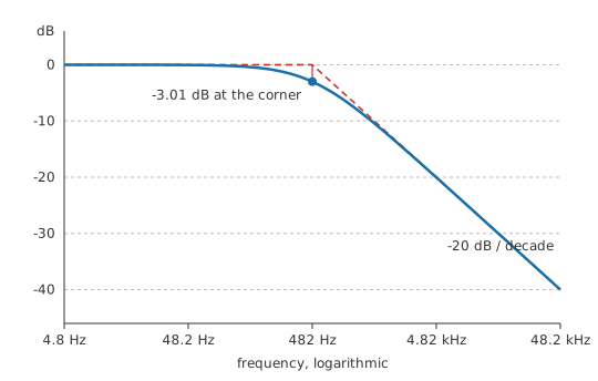
Those three points fix the whole curve: flat below the corner, straight at twenty decibels per decade well above it, and bending through the middle over a couple of decades either side. Sketching a response from a corner and a slope is what a Bode plot formalises.
Sections like this turn up wherever a signal has more bandwidth than the next stage wants. A pulse-width-modulated output becomes a slowly varying voltage once the switching frequency sits far enough above the corner, and a sensor feeding an analog-to-digital converter gets band-limited before it is sampled. On a slow digital input the same two parts are there to keep interference out of a stage with no business responding to it.
Checking one on the bench needs a function generator and a two-channel oscilloscope. Watch the input as well as the output, because the section's input impedance changes as the frequency does, and a generator with real output resistance will not hold its amplitude into a moving load. Scope probes matter here too: a probe on the output adds its own capacitance across the capacitor, and on a high-value section that is enough to move the corner while you are looking at it.
Engineer
A divider with one moving arm
The two arms of this divider do not add the way two resistors would. Current through a capacitor runs a quarter cycle ahead of the voltage across it, so the resistor's drop and the capacitor's drop peak at different moments and cannot be summed as numbers. Their magnitudes combine as the root of the sum of the squares, which is the series impedance of the pair:
No inductance is present in an RC section, so the inductive term is zero and what remains is the root of R squared plus X_C squared. The gain magnitude is then the share of that total which the capacitor holds: its reactance divided by the impedance magnitude of the two together.
Worked example — The divider route against the gain expression
Take the same section at 1.0 kHz, comfortably above its corner. The capacitor's reactance there is 723.4 Ω, and worked against the resistor that gives an impedance magnitude of 1.665 kΩ.
The capacitor's share of it is 0.434. Put the same frequency and the same corner into the gain expression instead and the answer is 0.434, which is -7.24 dB.
Those two routes are one piece of algebra written twice. Divide the top and the bottom of the divider ratio by the reactance, substitute the reactance expression, and the ratio of frequency to corner frequency appears on its own. The square root in the gain expression is the quarter-cycle offset between the two drops showing up in the arithmetic, and nothing else.
Magnitude is only half of the description. The output also lags the input, by an angle whose tangent is the ratio of frequency to corner frequency, which makes the lag zero far below the corner and a quarter cycle far above it. At the corner it is -45.0°, halfway between those limits, and by 1.0 kHz it has reached -64.25°. Two sections with identical magnitude curves can still behave differently, and a control loop or a stereo pair notices the phase long before the amplitude.
The model has edges. The expression describes one pole, and a network with two independent reactive components has a different shape that can rise above its low-frequency level before it falls, which a single RC never does. It assumes a steady sinusoid held long enough for the transient to die, so it says nothing about the first few microseconds after a step: that view of the same circuit is the RC time constant, and the two descriptions are linked by the same product of R and C. The parts are treated as linear and constant, so a capacitor whose value moves with the voltage across it falls outside the model. It assumes an ideal source and an unloaded output, which the next layer takes apart. And the straight lines drawn on the figure only approximate the curve: at the corner the two asymptotes meet three decibels above where the response passes, and they stay optimistic for about a decade in each direction.
Professional
Living with one pole
The resistance the capacitor sees
The R in the corner expression stands for the whole resistance the capacitor charges and discharges through, looking back from its own two terminals. It is a Thévenin resistance, and the marked resistor is only one contributor to it.
Source resistance adds to the series path.
Worked example — The same section behind a real source
Drive it from a source with 220 Ω of output resistance and the series path becomes 1.72 kΩ.
The corner falls to 420.6 Hz with neither marked component altered.
A load works the other way. Anything connected from the output to ground sits in parallel with the resistance the capacitor looks back into, which lowers that resistance and pushes the corner up. The same load also costs amplitude across the whole passband, because well below the corner the capacitor takes no part and the two resistances divide on their own.
Worked example — A 10 kΩ load hung on the output
Connect 10 kΩ from the output to ground. Seen from the capacitor, that load is in parallel with the series resistor, which gives 1.304 kΩ, so the corner climbs to 554.6 Hz.
Down in the flat region the same two resistances form a plain divider: 1.0 V going in leaves 0.870 V at the output, a loss of -1.214 dB that applies at every frequency the section passes.
Both shifts are easy to leave out of a hand calculation and neither shows up on the schematic. The way round them is either a series resistance small compared with the source and the load, which costs current, or a buffer at one end or both.
Two sections instead of one
A single pole is a slow way to reject anything. Forty decibels of loss arrives only two decades past the corner, which for this section means 48.2 kHz. Cascading two sections doubles the slope, and the pair does not keep the corner either section had on its own.
Worked example — Two of the same section, buffered from each other
A decade above the shared corner one section gives -20.04 dB, so two in series give -40.09 dB.
Each section is three decibels down at that shared corner, which puts the pair six decibels down there. The pair's own cutoff has therefore moved below it, to 310.4 Hz.
Those figures assume the second section draws nothing from the first. Without a buffer between them the second section is the load discussed above, so both the corner and the shape move, and the two-pole result has to be worked out as one network instead of two. An active filter solves that by putting an amplifier between the sections, and gets something a cascade of RC poles cannot: a response that peaks before it falls, which is how a sharper transition is bought. Band-pass and band-stop designs are built the same way, out of corners placed against each other.
Where the slope gives out
The falling straight line does not continue forever. A real capacitor has series inductance, in its own body and in the loop from the output node to ground and back, and above the frequency where that inductance resonates with the capacitance the shunt arm stops behaving as a capacitance and starts behaving as an inductance. Its impedance climbs from there, and the attenuation stops improving.
Take 8 nH of series inductance, an illustrative figure rather than a catalogue value, against the 220 nF capacitor already chosen. Those two resonate at 3.794 MHz, while the single-pole model is still confidently predicting -77.9 dB at that frequency. The resistor has a limit of its own, since a fraction of a picofarad across its body carries signal past it, though on a section of this impedance that one arrives well above the capacitor's resonance. Above a few megahertz the layout decides the answer more than the two component values do, which is one reason an RC intended as an EMI fix is drawn with the capacitor's return kept as short as the board allows.
Component choice matters over slower timescales as well. Class 2 ceramics lose a substantial fraction of their capacitance under DC bias and over temperature, and the corner rises to match, so a section that has to stay put wants a class 1 ceramic or a film part and the dielectric chosen on purpose. The resistor has a quieter cost: it contributes thermal noise to the output, and a high-value section makes a good aerial for whatever is radiating nearby.
Move the output from the capacitor to the resistor and the same two parts become a high-pass filter with the corner in the same place. Collect the whole response into one expression of frequency and it becomes a transfer function, which is where more elaborate filters are designed.
Common mistakes
- Choosing R without asking what drives the section — the source's output resistance joins the series path and drags the corner down with it. Work out the total series resistance first, then pick the capacitor.
- Leaving the load out of the sum — a load across the output raises the corner and flattens the passband at the same time, and the schematic shows neither. Compare the load with the section's own resistance before trusting the printed corner.
- Cascading two sections and keeping the original corner on the drawing — each section is three decibels down there, so the pair is six decibels down and its own cutoff has slipped below either one's. Recompute it, and buffer between the sections unless the second is far higher in impedance than the first.
- Reading the twenty-decibels-per-decade slope off the corner itself — that slope is an asymptote. It is three decibels away from the truth at the corner and still a little optimistic a decade out on either side.
- Assuming rejection keeps improving without limit — the capacitor's series inductance and the resistor's stray capacitance both put a floor under the attenuation, and past a few megahertz the layout sets that floor.
- Trusting a class 2 ceramic to hold the corner — its capacitance moves with bias, temperature and age. The corner follows it, in the direction that lets more through.
Frequently asked questions
Does a low-pass filter remove the high frequencies?
It attenuates them, which is a weaker claim. A single RC section still passes a measurable fraction of everything above its corner, and the fraction only shrinks in proportion to frequency. Anything that has to be genuinely absent needs either a corner placed decades below it or a filter with more poles.
How do I pick R and C for a corner I want?
Only the product is fixed by the corner, so choose the resistance first on other grounds: what the source can drive without sagging, what the next stage will load it with, and how much thermal noise the output can tolerate. Work the capacitance out from there, round it to a stocked value, and recompute the corner that pair really gives.
Why does the output lag the input?
The capacitor's voltage is the accumulated charge that has flowed into it, so it can only follow the input after some current has flowed. The lag grows from nothing well below the corner to a quarter cycle well above it, passing through half of that at the corner. It is the same physics that makes the two arms combine as a root of squares instead of a simple sum.
Will a bigger capacitor give a sharper cutoff?
No. It moves the corner down and leaves the slope where it was, since the slope belongs to the number of poles and not to the component values. Sharpness comes from more poles, from a resonant network, or from an active design.
Can the same section be used as a high-pass filter?
The same two parts can, with the output taken from the resistor instead of the capacitor. The corner stays where it was, because it depends on the product of the two values and both parts are still there. Which component the output comes from decides which half of the spectrum survives.