
Quick Answer
A band-pass filter passes frequencies between two corners and attenuates everything outside them, while a band-stop or notch filter does the reverse. A wide band comes from cascading a high-pass and a low-pass section; a narrow band or a deep notch needs a resonant LC network or an active design.
Intuition
Keeping the middle, losing both ends
A low-pass filter keeps what is slow and sheds what is fast. A high-pass filter does the opposite. Wire one after the other, with the high-pass turning over near the bottom of what you want and the low-pass near the top, and a signal has to satisfy both to reach the output. What survives is a band with an end on each side.
Telephone equipment works this way. Speech carries energy well outside the range a phone line passes, but the line keeps only a slice, conventionally about 300 Hz to 3.4 kHz. That is enough to carry words and to tell one voice from another, and narrow enough that a great many calls fit down one cable. Rumble below the slice and hiss above it never arrive at the far end.
The other job is the reverse of that one. Sometimes a single frequency is the problem and everything around it has to come through untouched. Hum picked up from the mains wiring is the standard case, and it sits at one frequency that barely moves. A filter shaped for that is a band-stop filter, or a notch when the rejected slice is narrow. It is built differently: instead of fencing a band in from both sides, it offers the unwanted frequency an easy path out of the signal that nothing else can use. A resonant pair of components provides that path.
Both shapes come in a loose version and a tight one. The loose version is two resistor-capacitor sections in a row: cheap, easy and wide. The tight one uses an inductor and a capacitor tuned to a single frequency, and it is fussy about staying where it was put.
Practitioner
Setting two corners around the wanted band
The cascade is the obvious construction and usually the right one. Feed the signal through an RC high-pass section, take its output into an RC low-pass section, and place the two corners so that the wanted band falls between them. Both corners come from the same expression, since both sections are the same two parts wired the other way up.
Neither corner should sit at the edge of the wanted band. Each section is already three decibels down at its own cutoff frequency, so the corners go outside the band with room to spare, and the capacitors then get rounded to stocked values and the corners recomputed from the parts that go in.
Worked example — Two corners around the telephony band
A high-pass section built from 470 nF in the signal path and 1.1 kΩ down to ground corners at 307.8 Hz, just under the bottom of the wanted band.
The low-pass section that follows it uses 47 kΩ in series with 1.0 nF to ground, putting its corner at 3.386 kHz, just over the top.
The centre of the band is the geometric mean of the two corners, 1.021 kHz, and the corner-to-corner width is 3.078 kHz. Centre divided by width is the Q of the band, here 0.332.
A Q below one describes a band wider than its own centre frequency, and a cascade of two single poles gives nothing narrower. Response magnitudes are quoted on the decibel scale, and a filter's gain is a ratio of two voltages:
Each section keeps the response its own lesson describes, and the cascade multiplies them. At the centre both sections are a little way into their roll-offs, so the peak of a wide band-pass never quite reaches the input: 0.917 survives, or -0.756 dB. At either section's own corner the pair together is 0.704, which is -3.046 dB. Outside the band each skirt falls at twenty decibels per decade, one pole's worth on each side.
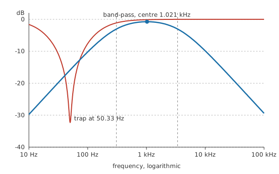
The notch on that figure is the other circuit, and it is built from an inductor and a capacitor in series, hung from the signal node to ground. Well away from resonance the branch has a large impedance and takes nothing; at resonance the two reactances cancel and the branch impedance collapses to almost nothing, shunting that one frequency away from the output. Where the collapse happens depends only on the two component values.
How wide the notch is depends on the losses in the loop, and the relationship between the two is the same one that governs any resonant circuit:
Worked example — A trap tuned to the mains frequency
1.0 H of inductance against 10 µF of capacitance resonates at 316.2 rad/s, which comes to 50.33 Hz once the radians are divided out.
An inductor that size is a wound component with resistance of its own. Take 25 Ω for it, an illustrative figure and not a catalogue value. The branch then has a Q of 12.65, so the notch measures 3.98 Hz between its half-power points.
Checking either circuit on the bench means sweeping a function generator while watching input and output on a two-channel oscilloscope. A notch this narrow needs small steps near its centre and a settled reading at each one, or the sweep will step straight over it.
Engineer
How sharp a cascade can get
Take the square root of the product of the two corners and something tidy happens to the ratios that drive the two sections. That frequency sits above the lower corner by the same factor as it sits below the upper one, so the high-pass works with a ratio and the low-pass works with its reciprocal, and the two magnitudes come out identical: 0.957 from the high-pass section, 0.957 from the low-pass. On a logarithmic frequency axis that point is the middle of the band, and it is the only middle worth quoting when the two ends are a decade apart.
The bandwidth quoted from the corner difference is a convenience, not a measurement. Half power means half the power at the peak, and the peak of this cascade is already below unity, so the frequencies at which the pair is three decibels down on its own best effort lie outside both section corners.
Worked example — Where the band really ends
Measured down from the peak instead of down from the input, the pair passes 263.4 Hz at the bottom and 3.96 kHz at the top.
That is a bandwidth of 3.694 kHz and a Q of 0.276, against the 0.332 the corner difference suggested. The geometric centre is unmoved: the true half-power points straddle it in the same proportion the corners do.
Push the two corners closer together and the passband narrows, but not without limit. With both corners on the same frequency the cascade is as selective as it can be, and its half-power points settle at 0.414 and 2.414 times that shared corner regardless of where the corner is. The Q that follows is 0.500, and no arrangement of two RC poles gets past it. Anything narrower has to buy its selectivity somewhere else.
A resonant branch is not bounded that way, and its depth is set by what is left when the two reactances cancel. At the resonant frequency the inductive and capacitive terms are equal and opposite in the series impedance, so the branch collapses to its own resistance and the circuit becomes a plain resistive divider at that one frequency.
Worked example — How far down the trap pulls its own frequency
Fed through 1.0 kΩ in series, the branch and that resistor divide the signal between them. At resonance the branch is nothing but the coil's winding resistance, so 1.0 V going in leaves 24.4 mV at the output.
As a ratio that is -32.26 dB, and it is the coil's losses that stop it going deeper. A lower-loss coil would make the notch both deeper and narrower, since the same resistance sets the depth and the width.
Off resonance the two reactances no longer cancel and the branch impedance climbs quickly, so a trap of this Q is over and done with inside a few hertz. Hum arrives at 50 Hz, a shade under the branch's own centre, and the trap there gives -32.14 dB instead of its full depth. The telephony band-pass, judged at the same frequency, leaves 0.160 of the hum in place, or -15.90 dB. Neither number is a fault. The band-pass skirt has simply not fallen far by the time it reaches the hum, because it was placed to define a band and never to reject one frequency.
The model has edges worth naming. It treats the two cascaded sections as independent, which holds only when something buffers them or their impedances are far apart, and Layer 4 puts numbers on that. It assumes a steady sinusoid held long enough for the transient to die out, so it describes neither what a narrow filter does to an edge nor how many cycles it needs to settle. The coil's losses are lumped into one fixed resistance, when winding loss climbs with frequency and a core adds more, so a measured trap comes out slightly shallower and slightly wider than the arithmetic. Both circuits are taken as linear, which excludes a core that saturates and a capacitor whose value moves with the voltage across it. And the skirts on the figure fall forever, where a real board runs into stray capacitance and lead inductance that put a floor under each one.
Professional
What a narrow band costs
Sections that load each other
The cascade's response is the product of two independent curves only if the second section takes nothing from the first. It always takes something, and how much decides whether the arithmetic in Layer 2 survives contact with the board.
Worked example — The low-pass section as a load on the high-pass
Down at the lower corner the low-pass capacitor is barely in the circuit. Its reactance there is 517 kΩ, eleven times the resistor it sits behind, so the following section presents that resistor and little else.
That resistance lands in parallel with the high-pass shunt resistor, giving 1.075 kΩ where the calculation assumed the marked part alone, and the lower corner climbs to 315 Hz.
A shift of that size is a rounding error next to component tolerance. It only stays small because the second section's resistance is more than forty times the first's, and the same pair built at matched impedances would halve the shunt resistance and double the corner. Either keep the impedance climbing along the chain, which costs noise and makes the high-value node a better aerial, or put a buffer between the sections and stop worrying. The general form of the problem is a Thévenin resistance looking out of each capacitor's terminals, and once several poles are being placed deliberately the whole thing gets written as a transfer function and solved as one network.
Buying a narrower band
Getting past a Q of one half means resonance or gain. Resonance is the passive route, and at audio frequencies it is expensive: the inductance in the worked trap is a physically large wound part, it picks up magnetic fields as readily as it filters them, and its own resistance sets a ceiling on Q that a small coil will not reach. Higher up the spectrum the same idea gets cheap and small, so tuned circuits belong to radio, and a crystal or ceramic resonator takes over wherever the Q has to be far beyond what a coil can reach.
Gain is the other route. An active filter wraps an amplifier around an RC network and gets a response that peaks before it falls, which no passive RC cascade can do. The RC band-pass at the heart of a Wien bridge oscillator is the same idea run to its conclusion: the network alone is broad and passes a third of its input at the centre, and the amplifier wrapped round it supplies the gain of three that the shortfall demands.
Sharpness is not free in either case. A filter that is narrow in frequency is slow in time, so a high-Q band-pass rings for many cycles after a step and a high-Q notch takes just as long to settle. Q and bandwidth works that exchange through in detail; a design wanting a sharp skirt and a quick settling time is asking for both ends of it at once.
Keeping a notch on its frequency
A trap only works while it is tuned, and its centre moves as the square root of the product of the two component values. A capacitor drifting a few per cent with temperature moves the notch by half that, and on a branch a few hertz wide half of a few per cent is enough to slide the rejection off the interference. Film capacitors and a stable coil are the usual answer where the notch has to stay put; where it does not, a broader and shallower trap is more reliable than a deep one that wanders.
The interference has its own opinion about frequency. Grid frequency is regulated closely but drifts a little with load, and hum is rarely a clean sine to begin with: a rectifier draws current in pulses, so a notch on the fundamental leaves the harmonics at two and three times the frequency completely untouched. Several stacked traps, or one broader stop-band, cover more of the problem than one very deep notch at the fundamental.
Reaching for a filter should also come after the other fixes have been tried. Interference that arrives through a shared return path is better dealt with at the ground than in a filter, and interference that arrives through the air is better dealt with by loop area and shielding, which is EMC work. A notch removes a known frequency from a signal that has already been contaminated, and every decibel it removes from the interference it also removes from anything wanted at that frequency.
Common mistakes
- Averaging the two corners to find the centre — a band-pass sits at the geometric mean of its corners, and on a band a decade wide the halfway point on a linear scale is nowhere near it.
- Quoting the corner difference as the bandwidth — the passband peak of a cascade is already below unity, so the real half-power points sit outside both corners and the band is wider than the subtraction says.
- Cascading two sections and treating them as independent — the second is a load on the first, which raises the lower corner and flattens the peak. Compare the two impedances, or buffer between them.
- Expecting a cascade to be selective — two RC poles cannot reach a Q above one half however the corners are placed, so a narrow band has to come from somewhere other than more RC sections.
- Treating the coil in a trap as pure inductance — its winding resistance sets the depth of the notch and its width at the same time, so a deeper notch is always a narrower one.
- Notching the fundamental and declaring the hum gone — mains interference carries harmonics, and a trap tuned to the fundamental passes every one of them.
Frequently asked questions
What is the difference between a band-pass filter and a band-stop filter?
They keep opposite halves of the same picture. A band-pass keeps the frequencies between two limits and sheds the rest; a band-stop keeps everything except the frequencies between two limits. A notch is a band-stop whose rejected slice is narrow enough to be aimed at one frequency.
Where is the centre frequency of a band-pass filter?
At the geometric mean of the two corners, which is the square root of their product. That is the point on a logarithmic axis where both sections attenuate by the same factor, so the response peaks there. The arithmetic mean only comes close when the band is narrow.
Can I build a notch without an inductor?
Yes. A twin-T network of three resistors and three capacitors notches deeply without any inductance, though the depth depends on close matching between the parts and the notch is broad unless an amplifier is wrapped around it. Active designs and digital filtering both remove the inductor as well.
Why does my notch filter leave some of the hum behind?
Usually the tuning. A narrow notch loses depth fast on either side of its centre, so a trap a hertz or two off the interference is much shallower than its specification suggests. Harmonics are the next suspect, since a trap on the fundamental does nothing at twice or three times that frequency. The resistance in the resonant branch also puts a floor under the depth, however well the tuning is done.
Does the order of the two sections in a cascade matter?
For the response, only through loading, and putting the higher-impedance section second keeps that small. For everything else it can matter a great deal: a high-pass placed first strips any DC offset before the next stage sees it, while a low-pass placed first keeps out-of-band energy away from whatever follows.