
Quick Answer
A Wien bridge feeds an amplifier's output back to both of its inputs. One path sets a gain of three; the other is an RC network that returns a third of the output, unturned, at exactly one frequency. The product is one at that frequency and less everywhere else, so that is the note the circuit holds.
Intuition
Exactly three, or nothing
Whistling is a sustained note produced by a system with no note of its own. Your lips and the cavity behind them prefer one pitch, air escapes at some rate, and you supply breath at whatever rate replaces what escapes. Blow harder than that and the note does not simply get louder: it jumps, or it rasps, or it stops. Blow softer and it fades. The steady note exists in a narrow band of effort and you find it without thinking.
An oscillator is the same arrangement with the same problem, and it is worth being precise about which part is hard. Choosing the frequency is easy: put something frequency-selective in the loop and the loop can only satisfy itself at one frequency. That much is general, and that lesson covers it for oscillators as a family.
What is specific here, and what makes a Wien bridge instructive rather than merely another circuit, is the effort. Its network returns exactly one third of what it is given, so the amplifier must supply exactly three. Not about three. Three.
The amplifier that does it is C18's invented part, unchanged: 200000 of open-loop gain, 1.0 MHz of gain-bandwidth product and 0.50 V/µs of slew rate on rails that swing to 13.5 V. Everything else here is invented for this lesson.
Practitioner
Two feedback paths, and only one of them is picky
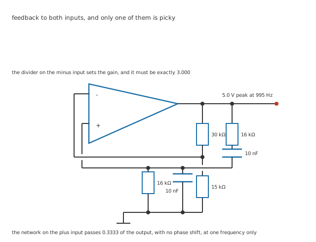
Seven junction dots and one deliberate break where the network's return crosses the divider column.
The output goes to two places. One is an ordinary resistive divider back to the inverting input, which sets a gain in the way every amplifier lesson describes. The other is the interesting one.
Worked example — What the network does and where
16 kΩ in series with 10 nF, feeding the same pair in parallel, is a band-pass with a very gentle peak. Its time constant is 160 µs, so it peaks at 995 Hz.
At that frequency it passes 0.3333 of what it is given, and turns the phase by nothing at all.
So the amplifier must supply 3.000, and 30 kΩ over 15 kΩ gives 3.000. The product round the loop is 1.000.
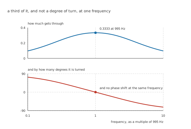
Both happen at the same frequency, and that coincidence is what makes this network the thing that chooses the note.
The phase panel is the half that matters and the half that gets left out. A network that passed a third of the signal but turned it thirty degrees would not sustain anything: the signal coming back would not line up with the signal going out, and the loop would find some other frequency where it did — or no frequency at all.
Engineer
Why a third, and why that is a knife edge
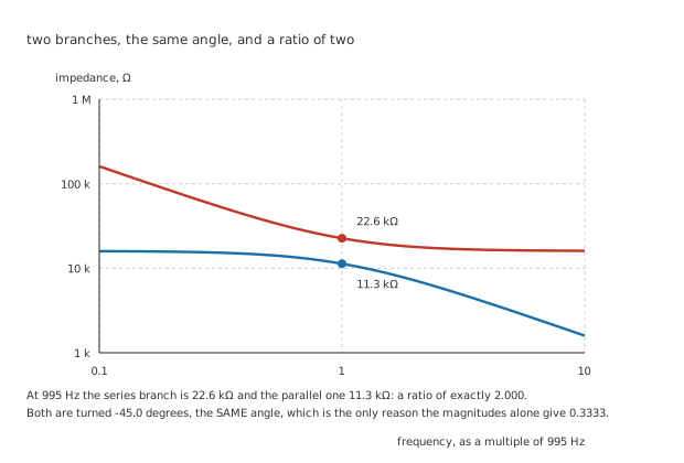
Their ratio is exactly two, which is the only reason the magnitudes alone divide to a third.
Worked example — Where the third comes from
At 995 Hz the series branch is 22.6 kΩ and the parallel branch 11.3 kΩ: a ratio of exactly 2.000.
The network is a divider, so it passes the lower over the sum of both, which is 0.3333.
That arithmetic is only legitimate because both branches are turned by the same -45.0 degrees at that frequency. At any other frequency the two angles differ and the magnitudes cannot simply be added.
And nothing else works, including the correct value held still
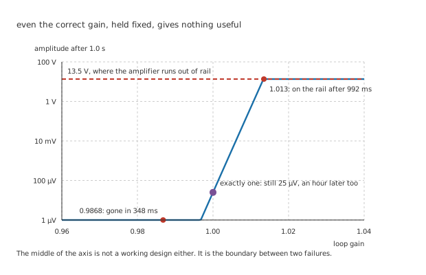
The middle of the axis is not a working design. It is the boundary between two failures.
This is where a Wien bridge stops resembling an ordinary circuit.
Worked example — What a fixed gain does
Start from 25 µV of noise. With the loop gain a little over one, the amplitude multiplies by that much every cycle, and at 1.013 it reaches the rail after 992 ms.
A little under one, it divides by that much every cycle: at 0.9868 it is down to a hundredth in 346.5 cycles, or 348 ms.
And at exactly one it neither grows nor shrinks. It stays at 25 µV — an hour later too.
There is no fixed gain that produces a useful output. The correct gain is not a working design; it is the dividing line between growing without limit and dying away, and sitting exactly on it means sitting at whatever noise happened to seed the circuit.
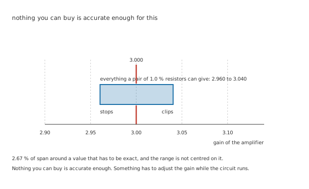
The band is nearly centred on the value that works, and that is no consolation.
Worked example — What ordinary resistors give you
Take 1.0 % resistors for both. The gain can land anywhere from 2.960 to 3.040, a span of 2.67 %.
That is a loop gain between 0.9868 and 1.013: at worst 1.32 % of decay per cycle, or 1.35 % of growth. Over 1.0 s, which is 995 cycles, the first is gone and the second has taken 987 cycles to reach the rail.
Ten times tighter resistors shrink the span by ten, which changes the numbers and not the problem. Temperature and ageing then move them anyway.
Professional
The gain has to be adjusted while the circuit runs
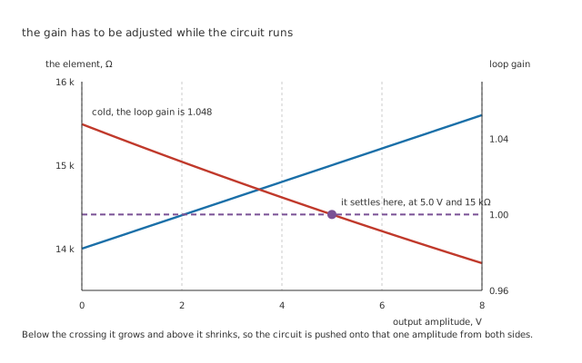
Below the crossing it grows and above it shrinks, so the circuit is pushed onto that one amplitude from both sides.
The answer is to stop trying to set the gain and let the circuit set it, by making the lower half of the divider something whose resistance rises with the amplitude passing through it.
Worked example — How the equilibrium forms
Cold, the element is 14 kΩ, so the gain is 3.143 and the loop gain 1.048 — 4.76 % of growth per cycle. From 25 µV of noise that reaches the working amplitude in about 262 cycles, or 264 ms.
As the amplitude rises the element warms and its resistance rises with it, at an invented 200 Ω/V.
At 5.0 V it reaches 15 kΩ, the gain is exactly 3.000, and the loop gain is 1.000. Any higher and the gain falls below three and the amplitude shrinks; any lower and it grows.
That is a genuinely different kind of design. The gain is not a value anybody chose: it is wherever the circuit's own arithmetic puts it, and the designer's job was to make sure that place exists and is stable. Classically the element is a small filament lamp, whose resistance rises several-fold as it warms; a thermistor with a positive coefficient does the same job, and a modern version rectifies the output and uses it to steer a transistor.
The stabilising element also sets the distortion, and the trade is direct. Make it respond quickly and it follows the waveform rather than its envelope, modulating the gain within each cycle and adding harmonics. Make it respond slowly and the output takes seconds to settle and lurches after any disturbance. A lamp works because its thermal time constant is naturally hundreds of cycles at audio frequencies, which is exactly the separation the job needs. An invented 0.10 % here is what a well-behaved one achieves.
What is not the limit here
Worked example — How far below the amplifier's ceilings this sits
At a gain of 3.000, the amplifier's 1.0 MHz allows 333 kHz — 335 times the oscillation frequency.
Its 0.50 V/µs allows a 5.0 V sine up to 15.9 kHz, which is 16.0 times.
Neither is close, which is why the amplifier's own limits do not appear in this design at all.
Push the frequency up by two decades and that changes. The slew limit arrives first, as it usually does, and it arrives as distortion rather than as a failure to oscillate — which is the awkward kind, because the circuit still works.
Reading one, and building one
Find the two feedback paths first. One goes to each input. If both go to the same input it is not this circuit.
Check the divider ratio is two, not three. The gain is one plus the ratio, and writing three into the ratio is the commonest error on paper.
Then find the stabilising element. If the lower resistor is an ordinary resistor, the circuit does not work and never did — it clips, and somebody has decided that is acceptable.
And expect the frequency to be approximate. The gain has to be exact and the frequency does not: 1.0 % components put 995 Hz out by a per cent or so, which for a test oscillator is fine and for anything measuring frequency is not.
Common mistakes
- Setting the divider to three instead of two — the gain is one plus the ratio, so 30 kΩ over 15 kΩ gives 3.000. A ratio of three gives a gain of four, and the output is on the rail within a second.
- Using ordinary resistors and expecting a sine — 1 % parts give anywhere from 2.960 to 3.040, which is 1.32 % of decay or 1.35 % of growth per cycle. Neither is an oscillator.
- Assuming the correct gain, held fixed, works — at a loop gain of exactly 1.000 the amplitude neither grows nor shrinks, so it stays at the 25 µV of noise that seeded it, for ever.
- Ignoring the phase half of the network's response — a third of the signal returned with thirty degrees of turn sustains nothing. Both conditions have to be met at the same frequency, and in this network they are.
- Making the stabilising element too fast — an element that follows the waveform instead of its envelope modulates the gain within each cycle and puts harmonics on the output. The separation between the two time scales is the design.
- Blaming the amplifier when it distorts at 995 Hz — its gain-bandwidth allows 333 kHz at this gain and its slew rate allows 15.9 kHz at this amplitude, 335 and 16.0 times over. The distortion is the stabilising element's.
Frequently asked questions
Why is it called a bridge?
Because the four elements — the two RC branches and the two divider resistors — form a bridge in the Wheatstone sense, with the amplifier's two inputs across its middle. Drawn that way the balance condition and the oscillation condition are the same statement, which is elegant and is not how anybody draws it in practice. The figure above is the practical arrangement and the two are the same circuit.
Why a third, rather than some other fraction?
Because the network is made of two equal resistors and two equal capacitors. At the frequency where the reactance equals the resistance, the series branch is the parallel branch's impedance times two and their angles match, so the divider gives one third. Make the two capacitors unequal and the fraction changes, along with the gain the amplifier must supply, and the arithmetic stops being memorable without buying anything.
Could I use a comparator's kind of positive feedback instead?
That is the same mechanism with a different amount. A comparator with hysteresis uses positive feedback with a loop gain far above one, so it slams to a rail and stays there — which is the point, because it is making a decision. Here the loop gain is held at one so the circuit does neither, and holds a sine instead. Same feedback, opposite design intent.
How stable is the frequency?
Only as stable as the components. The network has a very low quality factor — the magnitude peak is broad — so the frequency is set by R and C directly, and 1 % parts give roughly a per cent of error with temperature on top. That is the trade against an LC or crystal oscillator: a Wien bridge tunes easily over a wide range with a dual potentiometer, and holds its frequency badly.
Why does it take a quarter of a second to start?
Because the loop gain is deliberately small. At 4.76 % of growth per cycle it takes about 262 cycles to climb from 25 µV to 5.0 V, which is 264 ms — and the real figure is longer, because the loop gain falls as the amplitude approaches its equilibrium. An oscillator that starts faster is one with more excess gain, and it pays for that in distortion.