
Quick Answer
Electrical noise is the random voltage present in every circuit, set mainly by the thermal agitation of charge inside resistances. Its RMS value grows with the square root of resistance, temperature and bandwidth. Noise limits the smallest signal a circuit can resolve, and it is reported as a signal-to-noise ratio in decibels.
Intuition
Grain in a dim photograph
A photograph taken in poor light comes out speckled. The picture is there, but every point in it carries a small random error, and in the darkest corners of the frame that error is as large as what it was meant to record. Turn the lights up and the grain does not disappear. It stops mattering, because the picture has grown past it.
Circuits speckle the same way. Short the input of a sensitive amplifier with a resistor, connect nothing else at all, and the output still wanders. What comes out is noise: a small, random, endlessly changing voltage that no amount of careful construction removes. The charge carriers inside any resistance are in constant thermal motion, jostling harder the warmer the component is, and their jostling appears as a real if tiny voltage between its ends.
Noise is worth separating from interference straight away. Interference is a signal that belongs somewhere else and has arrived where it was not wanted: mains hum, or a switching supply's whine picked up along a cable. It has a source, and finding the source usually ends it. Noise has no source to find. It is a property of matter at any temperature above absolute zero, so the only useful questions are how big it is and whether the wanted signal sits comfortably above it.
For an ordinary 10 kΩ resistor at room temperature, listened to across the audio range, the answer is 1.80 µV. Small, and not negligible. A microphone preamplifier hisses at about that level, and no instrument reads below its own noise.
Practitioner
Putting a number on the noise floor
Boltzmann's constant in there is fixed by definition, and absolute temperature in kelvin barely moves in ordinary equipment: the gap between a cold room and a warm one comes to a small fraction of a decibel. The terms a design gets to choose are the resistance and the bandwidth. Both sit under a square root, which keeps them manageable and also caps what effort can buy — cutting either by a factor of a hundred improves the noise voltage by a factor of ten, and no further.
The answer comes out as an RMS voltage, the same measure a signal level is normally quoted in, so the two compare directly.
Worked example — The floor at a 10 kΩ source
An amplifier is fed from a source resistance of 10 kΩ, sitting at a room temperature of 293.15 K, and its own response limits the measurement to a bandwidth of 20 kHz.
The noise appearing at its input is 1.80 µV RMS. Nothing in the amplifier produced it, and no change to the amplifier will remove it.
Signal-to-noise ratio is how the comparison gets reported. Both quantities are voltages measured the same way, so the decibel figure takes the twenty-times form:
Worked example — A signal against that floor, and the cost of a bigger resistor
A sensor delivers 100 mV RMS into the same amplifier. Set against the floor of 1.80 µV, the ratio works out at 94.9 dB.
Now raise the source resistance to 1.0 MΩ. The signal has not moved, but the floor climbs to 18.0 µV, and the signal-to-noise ratio gives up 20.0 dB. All of that was settled by a component choice, before any amplifier was picked.
Datasheets rarely quote a bare noise voltage, because the figure means nothing until a bandwidth is attached to it. They give a noise density instead: the noise in one hertz, in volts per root hertz. Take the same resistance over 1.0 Hz and it comes to 12.7 nV, read as nanovolts per root hertz. Multiply a density by the square root of the bandwidth in use and the RMS figure comes back.
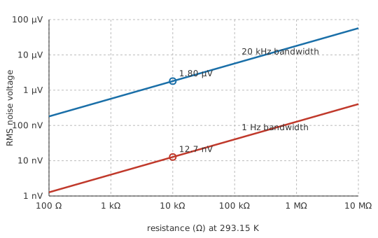
On the bench, the honest measurement is an RMS one. Noise on an oscilloscope shows as a fuzzy band, and the apparent height of that band keeps growing the longer the trace is watched, since a rare large excursion is only rare and not impossible. An RMS reading is the one that settles to a repeatable number.
Engineer
What the expression assumes
The relationship is not a curve fit. J. B. Johnson published his measurements from Bell Telephone Laboratories in 1928, and Harry Nyquist derived the same result that year from thermodynamics alone, so the noise carries both names. Nyquist's argument puts the resistor in thermal equilibrium with its surroundings and insists that whatever electrical power it delivers it must also absorb; anything else would let heat flow uphill. Boltzmann's constant, 1.380649 × 10⁻²³ joules per kelvin, has been exact by definition since the 2019 revision of the SI, so the only measured quantity left in the expression is the temperature.
The power form is worth following, because it accounts for the factor of four. A noisy resistance behaves as a noiseless resistance in series with a voltage source of the size the expression gives. Connect that to a matched load of equal resistance and the two split the voltage evenly, leaving 0.900 µV across the load in the worked case above. Power in a resistance follows the square of the voltage across it:
Put the half-voltage and the load resistance into that, and the four in the denominator cancels the four in the original expression, taking the resistance with it. What survives is Boltzmann's constant times the absolute temperature times the bandwidth. The available noise power comes out the same whatever the resistor is worth: -130.9 dBm over the bandwidth used above, for a megohm just as for ten kilohms. Resistance moves the noise voltage and leaves the noise power alone, so radio work quotes a noise floor as a power while audio work quotes it as a voltage. Noise power is real power in the sense AC power defines it: it heats the load, and none of it comes back.
The spectrum is flat: every hertz of bandwidth contributes the same mean-square voltage. Flatness is what makes a density figure meaningful, and it gives thermal noise its other name, white noise. Bandwidth therefore enters as a plain multiplier on the mean square and as a square root on the voltage. Narrowing a measurement from 20 kHz to 2.0 kHz drops the floor to 0.569 µV, which the decibel form reports as -10.0 dB. A tenfold cut in bandwidth is worth ten decibels, and bandwidth is usually the last term a design can still change.
The expression carries assumptions with it, and each of them is routinely dropped on the way to a number.
The bandwidth in it is the noise-equivalent bandwidth: the width of an ideal brick-wall filter that would pass the same noise power as the real response. A gradual roll-off keeps admitting noise above its corner, so a single-pole response has a noise bandwidth of 1.571 times its cutoff frequency. Substituting the −3 dB corner understates the floor by that margin.
Only the resistive part of an impedance generates thermal noise. An ideal capacitor or inductor stores energy and dissipates none, so it contributes nothing of its own; whatever noise appears across a reactive network comes from the real part of the impedance at each frequency, and the network then shapes it.
Independent sources combine as powers. Two equal uncorrelated contributions give a root-two rise in voltage, or 3.01 dB, so the largest single source dominates a total far more heavily than intuition suggests, and polishing anything ten decibels below it changes almost nothing.
The flat spectrum is also a classical result. It bends downwards where the photon energy becomes comparable with the thermal energy, which at this temperature falls around 6.11 terahertz. No ordinary circuit responds anywhere near there, so the flat form is safe for electronics. It remains an approximation with a stated range of validity.
Professional
Beyond the thermal floor
Thermal noise sets the floor, and several other mechanisms sit on top of it. Any current crossing a junction carries shot noise, because charge arrives in whole electrons at random instants instead of flowing as a smooth fluid; it grows as the square root of the current, so it dominates in photodiodes and anywhere the standing current is small. Flicker noise, also written 1/f noise, rises as the frequency falls and takes over below a corner belonging to the device and the process that made it. DC and low-frequency instrumentation lives inside that corner. A chopper amplifier gets around it by translating the signal up past the flicker region, amplifying it there and bringing it back down; an auto-zero part attacks the same problem by sampling its own low-frequency error and subtracting it.
Resistors add their own excess noise on top of the thermal figure whenever DC flows through them, and this part does depend on construction. Carbon composition is the worst of the common types and bulk metal foil among the best, with thin film in between. Look the manufacturer's noise index up rather than reaching for a rule of thumb, because it varies by orders of magnitude between the types. Picking a resistor type for a sensitive node is a noise decision as much as a tolerance one.
An amplifier contributes two quantities, and datasheets separate them deliberately. Input voltage noise appears in series with the signal and does not care what the source looks like. Input current noise flows through whatever the source impedance is and becomes a voltage there, growing in proportion to it. Their sum has a minimum at one particular source resistance, and op-amp families split along that line: bipolar parts for low source impedances, FET parts for high ones. An instrumentation amplifier makes the same trade at the front of a bridge or a sensor.
Radio and microwave work states all of this as a noise figure: how many decibels of signal-to-noise ratio a stage throws away, measured against a source producing nothing but its own thermal noise. The reference floor is the available power derived above, taken per hertz of bandwidth, and at this temperature that is -173.9 dBm. Physics fixes it, so the first stage in a receiver sets what the whole chain can hear and every stage after it counts for less.
Cooling helps, and less than people expect. The temperature term sits under the same square root, so halving the absolute temperature is worth only about three decibels. Radio astronomy and some detector work cool anyway, because at those signal levels three decibels justifies a cryostat; an ordinary circuit gains nothing measurable from a fan.
Digital conversion brings a floor of its own. A converter's quantisation steps put a small error on every sample, and resolution in the analog chain below that error is wasted. Averaging is the counterweight: uncorrelated noise falls as the square root of the number of samples combined, the same square-root law again, paid for in time instead of bandwidth.
Interference answers to none of this. Narrowing a bandwidth will not remove a tone sitting inside it, and no low-noise amplifier improves a layout. The fixes are physical: shorter loops, tidier returns, shielding and filtering at the boundary. EMI and EMC covers the coupling paths, ground loops covers the commonest of them on a bench, and decoupling capacitors alongside ferrite beads are where most of that work gets done.
Common mistakes
- A noise voltage quoted with no bandwidth attached — the number is unfinished on its own. Give the density in volts per root hertz, or name the band it was measured over.
- Using the −3 dB corner as the noise bandwidth — a gradual roll-off keeps letting noise through above the corner, so the noise-equivalent bandwidth is wider and the true floor sits higher than the corner suggests.
- Adding uncorrelated noise sources arithmetically — they combine as the root of the sum of the squares. Summing the voltages overstates the total, and the overstatement grows with every source added.
- Buying a low-noise amplifier for a megohm source — the source resistance is usually the dominant contributor there, and no amplifier can undo noise that was already present at its input.
- Treating a steady tone as noise — periodic interference has a source and a physical fix. Averaging and bandwidth reduction are the wrong tools for it.
- Reading a noise floor off a bench multimeter — a multimeter has input noise of its own and a bandwidth you cannot set, so the reading describes the instrument at least as much as the circuit.
Frequently asked questions
What is the difference between electrical noise and interference?
Noise is random and comes from the physics of the components themselves, so it can be reduced but never removed. Interference is a real signal from somewhere else that has coupled into the circuit; it has a source, and finding the source usually ends it. The two call for completely different fixes.
Does the type of resistor change its thermal noise?
No. Thermal noise depends only on the resistance value, the absolute temperature and the bandwidth, so a carbon resistor and a metal-film resistor of the same value are identical on that count. Construction matters for the excess noise a resistor adds when DC current flows through it, and there the spread between types is wide.
Can a filter remove noise?
Only by narrowing the bandwidth, which discards part of the signal along with the noise. Filtering helps when the wanted signal occupies less bandwidth than the measurement does. Where signal and noise overlap in frequency, a filter removes them together.
Why is thermal noise called white noise?
Its spectrum is flat: every hertz of bandwidth carries the same mean-square voltage, by analogy with white light containing all visible wavelengths in equal measure. Flicker noise is not white, since it climbs as the frequency falls.
Does cooling a circuit reduce its noise?
Yes, but slowly. Absolute temperature sits under the same square root as resistance and bandwidth, so halving it improves the noise voltage by about three decibels. Cryogenic cooling is worth the expense in radio astronomy and in some detectors, and is not worth it at all for ordinary equipment.
Knowledge check
A noise floor is quoted over a bandwidth of 20 kHz. What happens to it if the bandwidth is widened by a factor of four? (Show answer)
What is the thermal noise of a 100 kΩ resistor at 293.15 K over a bandwidth of 20 kHz? (Show answer)
A sensor delivers 100 mV RMS into a stage whose noise floor is 1.80 µV RMS. What is the signal-to-noise ratio? (Show answer)
A steady tone at the mains frequency appears in a recording made beside a transformer. Is that noise or interference, and will narrowing the bandwidth help? (Show answer)
Why do low-noise amplifier datasheets quote input noise in nanovolts per root hertz? (Show answer)
References
- National Institute of Standards and Technology, CODATA recommended values of the fundamental physical constants — the Boltzmann constant and the Planck constant, both exact by definition.
- Bureau International des Poids et Mesures, The International System of Units (SI), 9th edition — the 2019 revision that fixed the numerical value of the Boltzmann constant.
- J. B. Johnson, "Thermal Agitation of Electricity in Conductors", Physical Review 32, 97 (1928) — the measurement.
- H. Nyquist, "Thermal Agitation of Electric Charge in Conductors", Physical Review 32, 110 (1928) — the thermodynamic derivation.
- Paul Horowitz and Winfield Hill, The Art of Electronics, 3rd edition, Cambridge University Press — the chapter on low-noise design, for amplifier noise sources and optimum source resistance.