
Quick Answer
A ferrite bead is a sleeve of lossy ferrite threaded onto a conductor. At low frequency it behaves as a small inductor; above a crossover set by the material, its impedance turns resistive and absorbs high-frequency energy as heat instead of storing and returning it.
Intuition
Where the coil stops storing and starts absorbing
An ordinary inductor is a careful component. It takes energy from the circuit, holds it in a magnetic field, and hands it back later with as little waste as the designer could manage. Losses are the enemy and a good inductor has few of them.
A ferrite bead is made of the material an inductor designer would reject.
That is the whole idea. If you want to stop high-frequency rubbish travelling along a wire, storing it is no help at all — a store gives things back, and what comes back is the same rubbish slightly delayed. What you want is somewhere for it to go and not return from. Heat is the only such place.
So the bead is built from a ferrite chosen to be lossy at exactly the frequencies you want gone. Below those frequencies the material behaves itself and the bead is a small, well-mannered inductor with barely any impedance. Above them the material stops keeping up with the field, and the energy that goes in as magnetism comes out as warmth.
You do not wind it. A bead is a hollow cylinder with the wire pushed through the middle, which counts as one turn, and the ferrite does everything else.
The awkward part, and the reason this lesson has a fourth layer, is that a bead is still an inductor at the frequencies below its crossover — and an inductor next to a capacitor is a resonant circuit.
Practitioner
One turn through a lossy sleeve
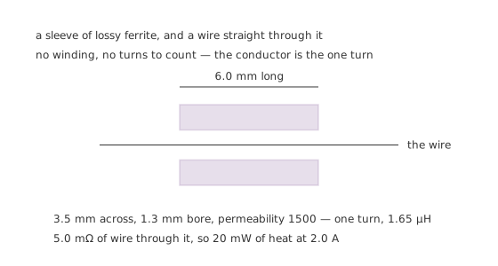
No winding, no turns to count — the conductor is the one turn.
Worked example — What the sleeve gives you
A sleeve 3.5 mm across with a 1.3 mm bore, 6.0 mm long, at an initial permeability of 1500, is a one-turn toroid. Its wall gives the cross-section and its mean circumference gives the path.
That works out at 1.65 µH of low-frequency inductance.
At DC the bead is nothing but the wire through it — 5.0 mΩ here, so 20 mW of heat at 2.0 A. A bead is transparent to the supply current it is fitted in, and that is the point of fitting it there.
The impedance is quoted at a frequency, always. A bead has no single value the way a resistor does. The catalogue number that looks like a value — a hundred ohms, six hundred ohms — is the magnitude of its impedance at some stated frequency, usually a hundred megahertz, and it means nothing without that condition.
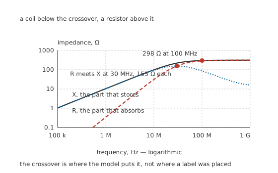
A coil below the crossover, a resistor above it.
Worked example — Three numbers at three frequencies
Follow the same bead up the band. At 1.0 MHz it is almost purely reactive: only 345 mΩ of resistance in a total of 10.4 Ω.
At 30 MHz the two parts are equal, 155 Ω each, which puts the magnitude at 220 Ω.
At 100 MHz the resistance has taken over — 285 Ω against 86.2 Ω of reactance, for 298 Ω in total. This is the number that would be printed on the reel.
The permeability, the crossover frequency and the sleeve's dimensions here are invented illustrations chosen to make the arithmetic legible. Every real bead's curve belongs to a specific ferrite grade and a specific geometry.
Engineer
Why a lossy material behaves like that
Permeability is usually taught as one number, and for a core running well below its limits that is enough. Push the frequency up and it stops being enough, because the material's response starts to lag the field driving it.
A lagging response splits into two parts: the bit that keeps up, which stores energy and returns it, and the bit that arrives late, which does not. Written as a complex permeability those are the real and imaginary parts, and they behave in opposite directions with frequency. The real part starts high and falls away as the material loses the ability to follow. The imaginary part starts at nothing, rises as the lag grows, and settles once the material has given up entirely.
That is the whole of the first figure. The reactance follows the real part, the resistance follows the imaginary part, and they cross where the two are equal — 30 MHz in this illustration, which is not a coincidence but the definition of the relaxation frequency the model is built around.
Below the crossover a bead is an inductor and behaves like one. That is not a small caveat. It is where the trouble comes from.
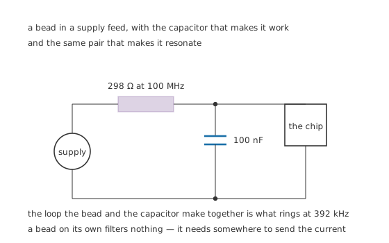
A bead on its own filters nothing — it needs somewhere to send the current.
A bead in a supply lead does nothing by itself. Impedance in series with a load only helps if there is a lower-impedance path for the unwanted current to take instead, and that path is the decoupling capacitor at the far end. Bead and capacitor together are the filter.
Bead and capacitor together are also a series resonant circuit.
Professional
The failure that catches everyone
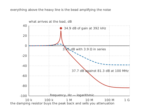
Everything above the heavy line is the bead amplifying the noise it was fitted to remove.
Worked example — A filter with 34.9 dB of gain in it
Feed the bead into a 100 nF ceramic capacitor of 20 mΩ series resistance and work the network's gain out from the two complex impedances.
Near 392 kHz the bead's reactance and the capacitor's cancel, leaving only the resistance in the loop — and down there the bead has almost none, 345 mΩ even at 1.0 MHz. What is left is 34.9 dB of gain, a factor of 55.6.
Higher up, where the bead is doing its job, the same network gives 81.3 dB of attenuation at 100 MHz. The bead works beautifully and makes things worse, at different frequencies, at the same time.
The reason this catches people is that both halves of it are invisible in the obvious test. Look at the supply rail with a scope and the high-frequency hash has gone, exactly as intended. The gain sits at a few hundred kilohertz, where a switching converter's own ripple lives, and it shows up as an unexplained rise in low-frequency noise that nobody attributes to the filter.
Worked example — What damping costs
Put 3.9 Ω in series with the capacitor and the loop has resistance in it at the resonance.
The peak falls from 34.9 dB to 3.41 dB, which is a network that no longer makes anything appreciably worse.
The price is attenuation where you wanted it: 37.7 dB at 100 MHz instead of 81.3 dB. Damping is not free, and the alternative ways of paying for it are a capacitor with real series resistance of its own, a second smaller capacitor, or a bead whose resistive region starts lower.
The other things a datasheet will not tell you plainly
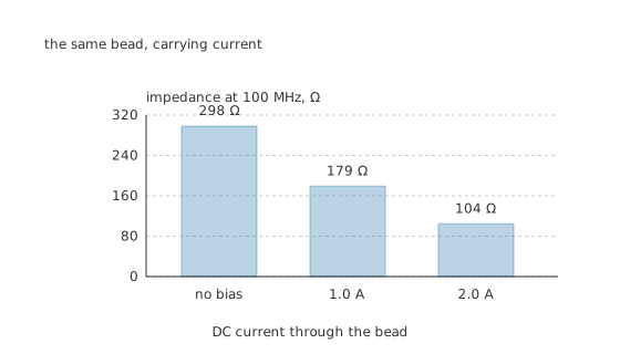
The same bead, carrying current.
A DC bias takes most of the impedance away. The ferrite partly saturates, the permeability drops, and both parts of the impedance drop with it. At a declared 0.60 retention at 1.0 A the bead gives 179 Ω, and at its rated 2.0 A a retention of 0.35 leaves 104 Ω. Choosing a bead by its zero-bias impedance and then running it at its rated current means getting about a third of what you chose.
The current rating is thermal and separate. It is set by the wire through the sleeve, and it says nothing about impedance. A bead can be well inside its current rating and useless.
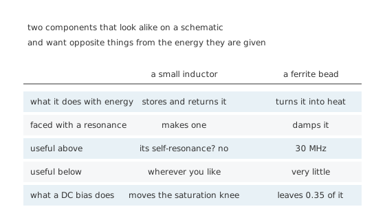
Two components that look alike on a schematic and want opposite things from the energy they are given.
A bead is the wrong component for a switching converter's inductor, and the reverse substitution is just as wrong. The two are drawn similarly, sit in similar places, and are chosen against opposite criteria.
Fit it at the pin, not at the connector. The impedance only helps for current that would otherwise have travelled past it, so a bead upstream of a long track has a long track's worth of antenna on the wrong side of it. This is a layout problem dressed as a component choice, and it is why board-level noise is a subject of its own.
Signal-line beads and power-line beads are different parts. A signal bead has to preserve the edges of what passes through it, so its impedance is chosen to start well above the signal's own harmonics; a power bead only has to pass DC. Fitting a power bead on a fast signal line rounds every edge in the system.
Where this arrives next
Two beads wound as a pair on one core become a common-mode choke, which attacks a noise current that a single bead in one lead cannot reach.
Common mistakes
- Treating the catalogue impedance as a value — 298 Ω here is the magnitude at 100 MHz and nothing else. At 1.0 MHz the same bead is 10.4 Ω.
- Fitting a bead without a capacitor — series impedance only diverts current that has somewhere better to go. The bead and the decoupling capacitor are one filter, not two components.
- Missing the resonance — this bead and a 100 nF capacitor peak at 34.9 dB of gain at 392 kHz, right where a converter's ripple lives, while attenuating 81.3 dB at 100 MHz exactly as intended.
- Ignoring the DC bias — at the rated 2.0 A this bead retains 0.35 of its impedance, 104 Ω instead of 298 Ω. The current rating is about heat and says nothing about that.
- Using a bead as an energy-storage inductor — it is built from material chosen to lose energy, which is the opposite requirement.
- Fitting it at the connector instead of the pin — everything downstream of the bead is still connected to the noise source through the track you left on the wrong side of it.
Frequently asked questions
What does the number on a ferrite bead mean?
It is the magnitude of the impedance at a stated frequency, almost always 100 MHz. The bead here is a 298 Ω part on that convention, made up of 285 Ω of resistance and 86.2 Ω of reactance. At 1.0 MHz the same part is 10.4 Ω, and at DC it is 5.0 mΩ of wire.
How is a bead different from a small inductor?
An inductor stores energy and returns it; a bead turns it into heat. Below its crossover a bead behaves as an inductor anyway — here the resistance is only 345 mΩ at 1.0 MHz — and above the crossover at 30 MHz the resistive part dominates. That is where the filtering comes from.
Can a ferrite bead make noise worse?
Yes, and it is common. Below its crossover the bead is a low-loss inductor, so with a 100 nF decoupling capacitor it forms a series resonance at 392 kHz with 34.9 dB of gain — a factor of 55.6. Damping it with 3.9 Ω brings the peak down to 3.41 dB and costs attenuation higher up, 37.7 dB at 100 MHz instead of 81.3 dB.
Why does the impedance drop when current flows through it?
The ferrite partly saturates and its permeability falls, taking both the resistive and the reactive parts with it. This bead keeps a declared 0.60 of its impedance at 1.0 A and 0.35 at its rated 2.0 A, so 298 Ω becomes 104 Ω at the current it is sold for.
Where should the bead go?
In series with the pin it is protecting, with its capacitor immediately after it, as close to the load as the layout allows. Any track between the bead and the load is on the unprotected side and can pick up or radiate whatever the bead was fitted to stop.