
Quick Answer
An inductor is a coil of wire, usually wound on a magnetic core, sold with a specified inductance. The core decides how many turns that inductance needs, and the turns decide the winding resistance. Above a certain current the core stops working and the inductance collapses.
Intuition
The component you can make by accident
Wind a wire into a coil and you have made an inductor. Nobody has to add anything. That is unusual: a resistor needs a resistive film deposited on a former, a capacitor needs two conductors held apart by a dielectric, but inductance appears the moment a conductor encloses any area at all. A straight wire has some. A loop of hookup wire has more. A track that goes the long way round a board has more still.
So the component sold as an inductor is not doing something exotic. It is doing something every piece of wire already does, arranged so that it dominates everything else the part might be.
The thing being arranged is a magnetic field. Current through the coil sets up a field, and the field holds energy. Change the current and the field has to change with it, and changing the field takes voltage. That is the whole behaviour, and it is the whole product: an inductor makes changes of current expensive.
What you buy, then, is a number of henries, and what you get with it is a piece of copper and a lump of magnetic material. The copper has resistance. The magnetic material works up to a point and then stops. Neither of those was what you wanted, and both of them decide whether the part is any good in your circuit.
Inductance is the property. This lesson is about the object.
Practitioner
Six numbers on one line
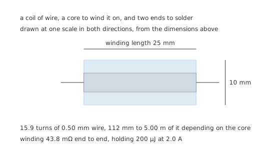
The core runs through the middle of the winding, and the two ends are what you solder.
Buying an inductor means reading a catalogue line. Six numbers matter, and each of them forbids something.
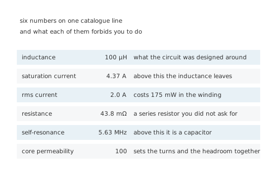
None of these is optional, and the last four are the ones people skip.
That relation is where the turns come from. Fix the inductance you want, fix the shape of the former, and the number of turns falls out of the core's permeability — high permeability, few turns.
Worked example — The same inductance, three cores
Take 100 µH on a former 25 mm long and 10 mm across.
Air-cored, the solenoid relation solved for the turn count asks for 159 turns. On a drum of relative permeability 100 it asks for 15.9, and on a toroid of relative permeability 2000 it asks for 3.56.
Turns go as the reciprocal square root of the permeability, so twenty times the permeability buys a little over four times fewer turns.
The permeabilities, the former's dimensions and the wire gauge here are illustrations chosen to make the arithmetic legible, not figures read off any real part. Every catalogue number is specific to the part in front of you.
Reading the part itself is harder than reading a resistor. Wirewound axial parts sometimes carry colour bands in microhenries, and small surface-mount parts carry a three-digit code where the last digit is the number of zeros, so 101 means 100 and 4R7 means 4.7. Plenty of parts carry nothing at all, because a shielded drum has no room for printing and the manufacturer expects you to know what you fitted. If you have an unmarked coil and need its value, an LCR meter will tell you — and it will tell you at one test frequency, which for a part with a low self-resonance is a real caveat rather than a formality.
The package tells you more than the marking does. An unshielded drum is two flanges with a winding between them and the field spilling out of both ends. A shielded drum has a magnetic sleeve around that winding. A toroid keeps the flux inside a closed ring and leaks least of all, at the cost of being awkward to wind and awkward to mount. Moulded and multilayer chip parts sit at the small end, where the whole component is a few tenths of a millimetre thick and the inductance is measured in nanohenries.
Typical values sort themselves by job. Nanohenries to a few microhenries for radio work; tens to hundreds of microhenries for switching converters; millihenries and upwards for mains-frequency filtering and audio. The value alone does not tell you which job a part was built for, which is what the rest of the line is for.
Engineer
What the core costs
Fewer turns means less wire, and less wire means less resistance. The winding is a resistor whether you wanted one or not, and it is in series with everything the inductor does.
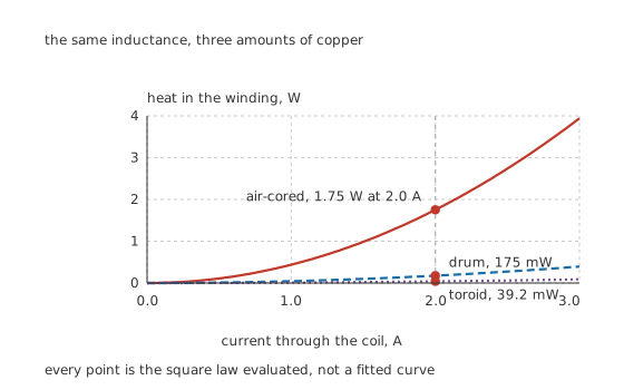
Three square laws, differing only by how much copper each construction needs.
Worked example — What the copper costs at the working current
One mean turn of that former is its circumference, so the air-cored version needs 5.00 metres of 0.50 mm wire and the toroid needs 112 mm.
At a copper resistivity of 17.2 nΩ·m that is 438 mΩ against 9.79 mΩ, with the drum between them at 43.8 mΩ.
Run 2.0 A through each and the heat is 1.75 W, 175 mW and 39.2 mW — a spread of 44.7 times, which is exactly the ratio of the turn counts because resistance follows wire length directly.
So far the high-permeability core wins on every count. It does not, and the reason is the second half of the same equation.
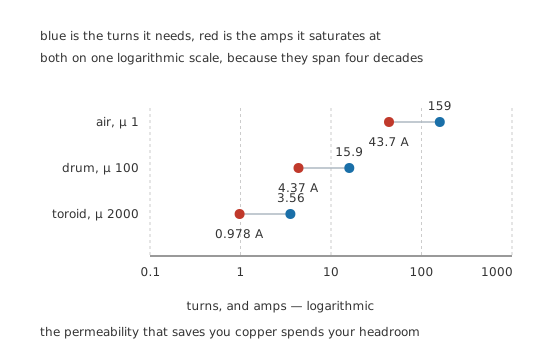
The permeability that saves you copper spends your headroom, by the same factor.
Worked example — Where each construction runs out
The magnetic material has a ceiling. Take an illustrative 350 mT and read the flux-density relation backwards for the current that reaches it.
The drum saturates at 4.37 A and the toroid at 0.978 A, a factor of 4.47 apart.
Empty space has no ceiling to hit, so the air-cored figure of 43.7 A is not a limit at all — it is what the same geometry would need if it had one, printed here only so the three can be compared on one axis.
Flux density goes as the permeability times the turns, and turns go as the reciprocal square root of permeability, so the product goes as the square root. Twenty times the permeability costs you the same four-and-a-bit factor of current headroom that it saved you in turns. There is no free version of this trade, which is why inductor types is a real subject rather than a catalogue.
Professional
Choosing one, and the two numbers that catch people out
Selection starts with the two currents, not with the inductance. The inductance is usually decided for you by the circuit; what is not decided is whether the part survives.
Saturation current is a cliff, not a derating. A resistor run past its rating gets hot and drifts. An inductor run past saturation stops being an inductor, and it does so within microseconds. The current that was being held back is suddenly held back by nothing but the winding resistance, and in a switching converter that is a short circuit across the switch. Saturation deserves its own lesson because the failure is that abrupt.
RMS current is a thermal rating and behaves like one. It is the current at which the winding's own heat lifts the part to whatever temperature rise the manufacturer chose, and like every thermal rating it shrinks in a hot enclosure. Two parts with the same inductance and the same saturation current can differ by a factor of ten in winding resistance.
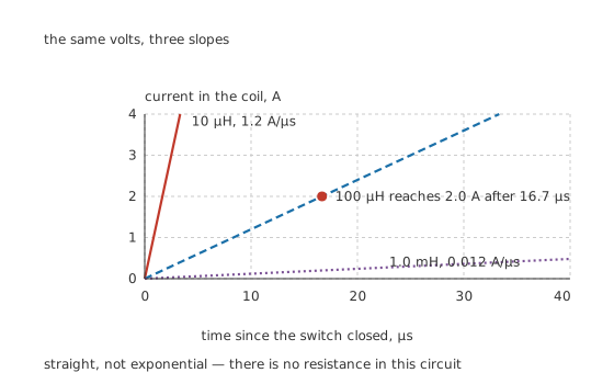
Straight lines, because there is no resistance in this circuit to bend them.
Worked example — Whether the value suits the switching rate
Hold 12 V across the coil and the current ramps at a rate the inductance sets: 1.2 A/µs for 10 µH, 0.12 A/µs for 100 µH and 0.012 A/µs for 1.0 mH.
At that middle rate the current needs 16.7 µs to climb to 2.0 A, which is what fixes the shortest switching period the value can serve.
The energy in the field at that current is 200 µJ, and it has to go somewhere when the switch opens.
Above its self-resonance the part is a capacitor. Turn-to-turn capacitance sits across the whole winding, and it resonates with the inductance.
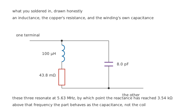
The junction between the inductance and the resistance reaches neither terminal.
Worked example — Where the coil stops being a coil
An illustrative 8.0 pF of winding capacitance across 100 µH resonates at 5.63 MHz.
By that frequency the reactance has climbed to 3.54 kΩ, and above it the impedance falls again as the capacitance takes over.
A part chosen to block noise at ten times its own self-resonance is not blocking anything, which is why ferrite beads exist as a separate component.
Shielding is a system decision, not a part decision. A drum core leaks field into whatever is next to it on the board, and a toroid or a shielded part mostly does not. If the leaked field lands on a sensitive node, the part that measured well on the bench misbehaves in the product.
Tolerance is looser than you are used to. Ten and twenty per cent are ordinary for power parts, because turns come in whole numbers and cores vary batch to batch. A filter designed to a corner frequency with no margin will not hold it.
Where this arrives next
The core is the next subject: what the materials are and what each is for, then what happens at the cliff. Two turns down the same road, the same coil with a lossy core becomes a ferrite bead, and two coils on one core become a transformer.
Common mistakes
- Reading only the inductance — the same 100 µH here comes with 9.79 mΩ and 0.978 A on one core and 438 mΩ and 43.7 A on another. Those are different components with the same headline number.
- Treating saturation current as a derating figure — it is a cliff. Past it the inductance leaves within microseconds, and the winding resistance is all that remains in the way.
- Ignoring the winding resistance in a power path — 2.0 A through 438 mΩ is 1.75 W of heat that has to leave the part.
- Assuming a bigger core is always better — a higher permeability cuts the turns from 159 to 3.56 and cuts the saturation current from 43.7 A to 0.978 A by the same factor.
- Using a part above its self-resonance — 8.0 pF across 100 µH resonates at 5.63 MHz, and above that the part passes high frequencies instead of blocking them.
- Forgetting that the field leaves the part — an unshielded drum couples into whatever is beside it, which is a board-layout problem rather than a component problem.
Frequently asked questions
Why does the same inductance come in so many sizes?
Because the core sets the trade. On this former, air needs 159 turns and saturates at nothing in particular; a permeability of 2000 needs 3.56 turns and saturates at 0.978 A. Fewer turns means less copper and less heat, and it also means less current before the core gives up.
What happens when an inductor saturates?
The magnetic material stops responding to more current, so the inductance collapses and the part behaves as its winding resistance. In this example that is 43.8 mΩ on the drum, which across a supply is close enough to a short circuit to destroy whatever is switching it.
How much does the winding resistance really cost?
At 2.0 A the three constructions here dissipate 1.75 W, 175 mW and 39.2 mW — a spread of 44.7 times, from nothing but how much wire each one needs. In a supply that is the difference between a warm part and a scorched one.
What is self-resonance and when do I care?
Every winding has capacitance between its turns, and it resonates with the inductance. Here 8.0 pF and 100 µH resonate at 5.63 MHz, where the reactance has reached 3.54 kΩ. Below that the part is inductive; above it, capacitive. You care whenever the signal you are filtering is anywhere near that frequency.
How do I know if a value suits my switching frequency?
Work out the ramp rate. With 12 V across 100 µH the current climbs at 0.12 A/µs, so reaching 2.0 A takes 16.7 µs. If your switching period is much shorter than that the current never gets there; if it is much longer, the current overshoots into saturation.